Memory Card
We have seen how inductive proximity sensors works. Now we can go instead to the other possibility: I take into account the fact that there is no excitation.
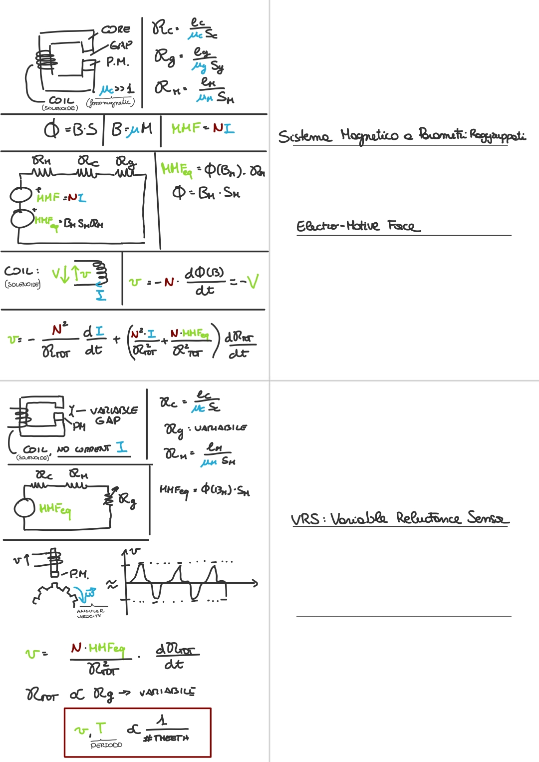
Here’s a VRS (variable reluctance sensors):
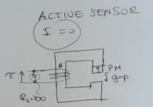
- When speaking about this usually we think to a structure where there is no external excitation.
⇒ So an active sensor. - For semplicity (and also because it’s a good approximation) I consider .7
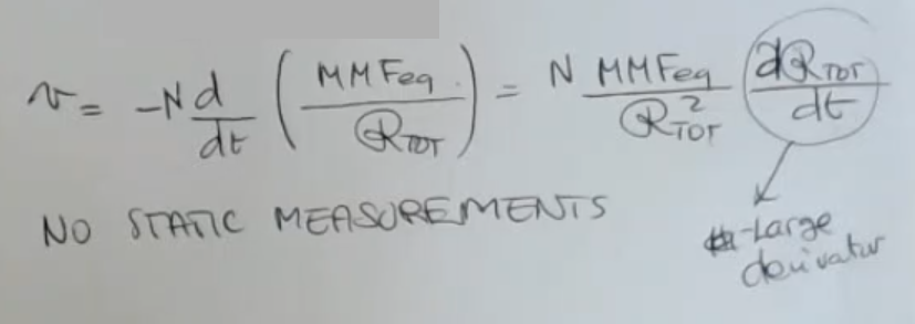
In this case we have to forget the part which depends on the current, so we will get an output voltage equal to:Where:
- is the electro-motive force (this is actual voltage measured in Volts, but has sign inverted with rispect to the actual voltage drop).
- : equivalent magneto motive force.
- : total reluctance
And if I use a very large resistance , for example tanks to an amplifier, then actually I will have a very small current, and the assumption , is true in general. So not only because I don’t force a current, but also there is no current induced in the circuit due to the very large impedance at the sensing coil.
IMPORTANTE So in this case to generate a voltage I need a varying reluctance, so the drawing doesn’t show it but I need the gap length to change.
We have also seen a variable reluctance sensor used to measure speed, or anglular speed: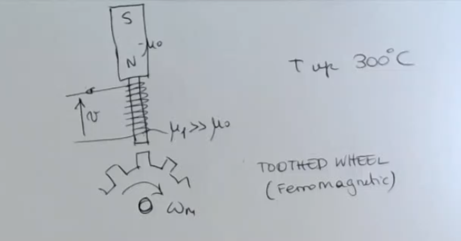
This is its lumped parameter model: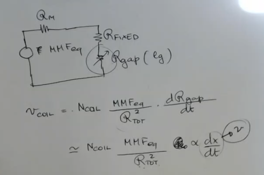
So while the thoothed wheel rotates this will be the plot of :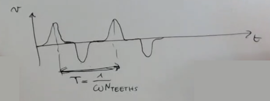
- The period is given by the angular rotation between two theeth, the more theet the wheel has, the lower will be the period:Where:
- (previously called ) is the angular velocity.
- : number of theets.
- We need to mention that also the amplitude of the graph will scale with , not just the period.
This can be a problem, because we will have a good signal to noise ratio (SNR) when the machine is rotating fast, and a lower one when it rotates slow.
If the machine is still the only thing I will measure will be the noise.
- We need to mention that also the amplitude of the graph will scale with , not just the period.