List of things to memorize:
SaM - Problems and Possible Solutions
Link to original
- General Solution for DC Errors and Low Sensitivity:
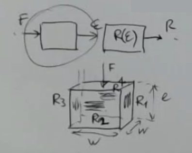
- SaM - Definition of a Resistive Bridge • Balanced Bridge • Thevenim Equivalent of the Resisitive Bridge
- SaM - Design of a Resistive Bridge
- SaM ~ Resistive Bridge Example • Strain Gauge
- SaM - Half Bridge • Calculation for the Maximum Sensitivity of a Resistive Bridge
- SaM ~ Half Bridge Example • Two Strain Gauges
- SaM - Full Bridge
- SaM - Types of Resistive Bridge Recap
- SaM - Wire Resistance in a Resistive Bridge (2 and 3 Wires Layout)
- SaM ~ Complete Sensor • Load Cell with a Resistive Bridge
- SaM ~ Complete Sensor • Accelerometer with a Resistive Bridge
- Problem: SaM - 2 Wires Measurement with Wire Resisitances
⇒ Solution: SaM - 4 Wires Measurement with Wire Resisitances- Problem & Solution: SaM - Remove the Offset in the Measurement System
- Problem & Solution: SaM - Non-Ideal Operational Amplifier • OZE (Out of Zero Error) • Special Kinds of Operational Amplifiers • Precision Amplifier • Low Noise • Low Input Bias Current • Zero Drift • Low Noise Operational Amplifier
- Problem: SaM - Self-Heating
⇒ Solution: SaM - Reduce the Effect of Self-Heating- Problem & Solution: SaM - Coupling with the Environment (and Solution)
- Problem: SaM - Electrical Noise
⇒ Solutions:
Transclude of SaM---MEMORIZE-(Resistive-Bridge-•-Wheatstone)#sam---definition-of-a-resistive-bridge--balanced-bridge
SaM - Design of a Resistive Bridge
- We take in example an half bridge.
- Set the output range , from this find .
- Check the power (self heating):
- Check accuracy or maximum error:
- Linearity of the bridge: so if .
The non-linearity error:So assert that:
Link to original
SaM ~ Resistive Bridge Example • Strain Gauge
- Example of the design process of a ” balanced resistive bridge” using a single strain gauge sensor.
- (1.) Find :
⇒- (3.) Check accuracy or maximum error:
⇒
Then:And for we obatain:
Link to original
SaM ~ Half Bridge Example • Two Strain Gauges
- Structure:
- Sensors formula (with temperature offset):
- Output formula:
Link to original
/../../Notes--and--Images/Pasted-image-20230611201143.png)
/../../Notes--and--Images/Pasted-image-20230611201132.png)
SaM - Half Bridge • Calculation for the Maximum Sensitivity of a Resistive Bridge
- Circuit:
- Sensors:
- K-ratio:
- Output formula:
- For: , and :
- Maximum Realative Sensisitivity :
- Calculate the maximum relative sensitivity:
- Calculate:
- Calculate , than calculate:
- Find such that:
- Find such that is maximied: and you’ll find .
- Calculate :That’s why it is called “half” brige.
Link to original
/../../Notes--and--Images/Pasted-image-20230611200647.png)
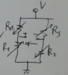
SaM - Types of Resistive Bridge Recap
- bridge:
- bridge:
- bridge:
- ALL BRIGES reject the common mode disturbances (DC errors).
- The half-brige has improved relative sensitivity, it is linear for .
- The full-brige has even more relative improved sensitivity, it is always linear.
SaM - Full Bridge
- Circuit:
- Sensors:
- Output formula :
- Maximum Realative Sensisitivity :
Link to original
/../../Notes--and--Images/Pasted-image-20230625114341.png)
SaM - Wire Resistance in a Resistive Bridge (2 and 3 Wires Layout)
- Circuit:
- Output formula:
- Offset and sensitivity:NOT_SURE_ABOUT_THIS (redo the sensitivity calculations)The offset in theory could be corrected.
The sensitivity is different from the nominal one (it depends on ).- Using a current suplly - circuit:
- Formulas:
The sensitivity is constant, this is a linear sensor (good).
The offset still depends on (bad).
==This is a good solution for AC measurements==.- 3 wires layout - circuit:
- Formulas:NOT_SURE_ABOUT_THIS (redo the sensitivity calculations)We have removed the offset (good).
But the sensitivity still depends on (bad).
Link to original
/../../Notes--and--Images/Pasted-image-20230625114046-1.png)
/../../Notes--and--Images/Pasted-image-20230625114138.png)
/../../Notes--and--Images/Pasted-image-20230625114149-1.png)
SaM ~ Complete Sensor • Load Cell with a Resistive Bridge
- Structure:
- Electrical model:
- Formulas:
- Strain gauge general formula:
- Specific formula for the four strain gauges:
- Resisitive bridge formula:
- Final formula:Or:
- Real World Measures:
- usually .
SaM ~ Complete Sensor • Accelerometer with a Resistive Bridge
- Strucutre:
- Sensor formulas:Where:
- Considering the pre-deformation of the straing gauges:
Link to original
/../../Notes--and--Images/Pasted-image-20230625114240.png)
SaM - 2 Wires Measurement with Wire Resisitances
- Structure:
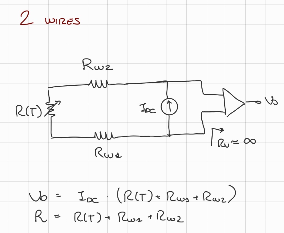
- Total resistance formula:
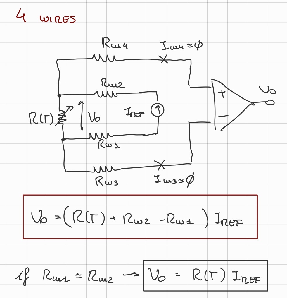
SaM - 4 Wires Measurement with Wire Resisitances
- Structure and formula:
SaM - Remove the Offset in the Measurement System
- Linear sensor (~Ex.: RTD) equation, taken within :
- Simplest read-out electronics:
- Output formula:
- Output graph:
- Formulas:Where:
- is taken as .
- can be seen as the offset of the system.
- While is its dynamic range.
- The information given by the sensor lies all in this small range that we will call .
- Problem: we don’t fully utlize the range given by the acquisition system (A/D).
Solution: compensate the offset, so bring the output signal to have a :- Using a balanced bridge:
- Problem: we might need to consider the wires resistances.
- Problem: we have corrected the offset, but we cannot correct the drift, which is usually taken as:
Link to original
/../../Notes--and--Images/Pasted-image-20240116182444.png)
/../../Notes--and--Images/Pasted-image-20240116182412.png)
/../../Notes--and--Images/Pasted-image-20240116183300.png)
/../../Notes--and--Images/Pasted-image-20240116183919.png)
/../../Notes--and--Images/Pasted-image-20240116184017.png)
Transclude of SaM---MEMORIZE-(Amplifiers)#sam---non-ideal-operational-amplifier--oze-out-of-zero-error
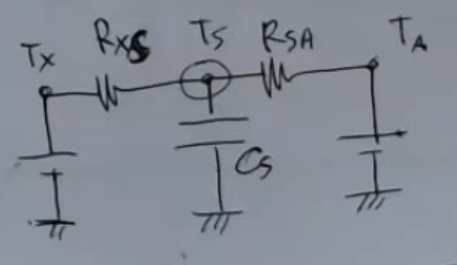
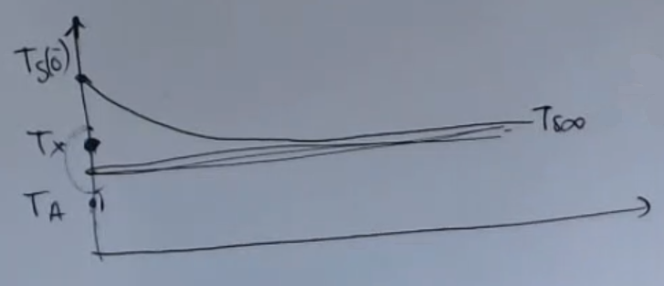
SaM - Self-Heating
- Simple lumped thermal parameter system:
- Meaured temperature at regime:
- Measurement error:
SaM - Reduce the Effect of Self-Heating
-
Using a “train of pulses”:
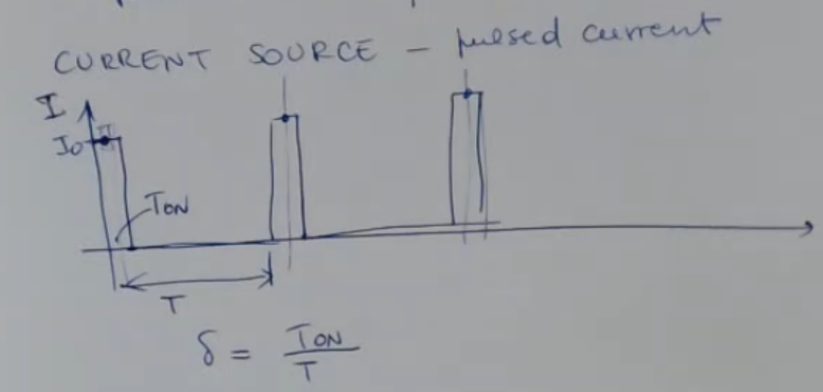
-
Calculations:
- the self-heating depends directly on the average power :
- If we perform the calculation:
- While respect to the DC approach:It is reduced by a factor decided by the duty cycle .
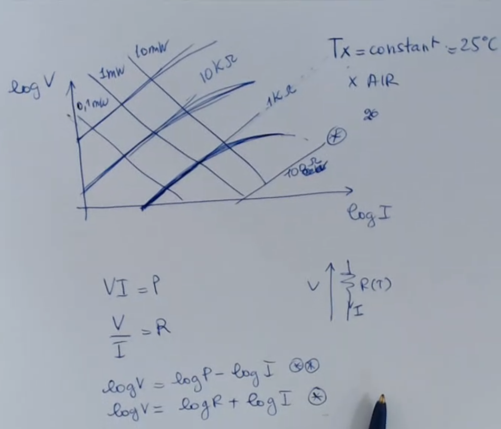
-
Logaritmic voltage-current-power graph:
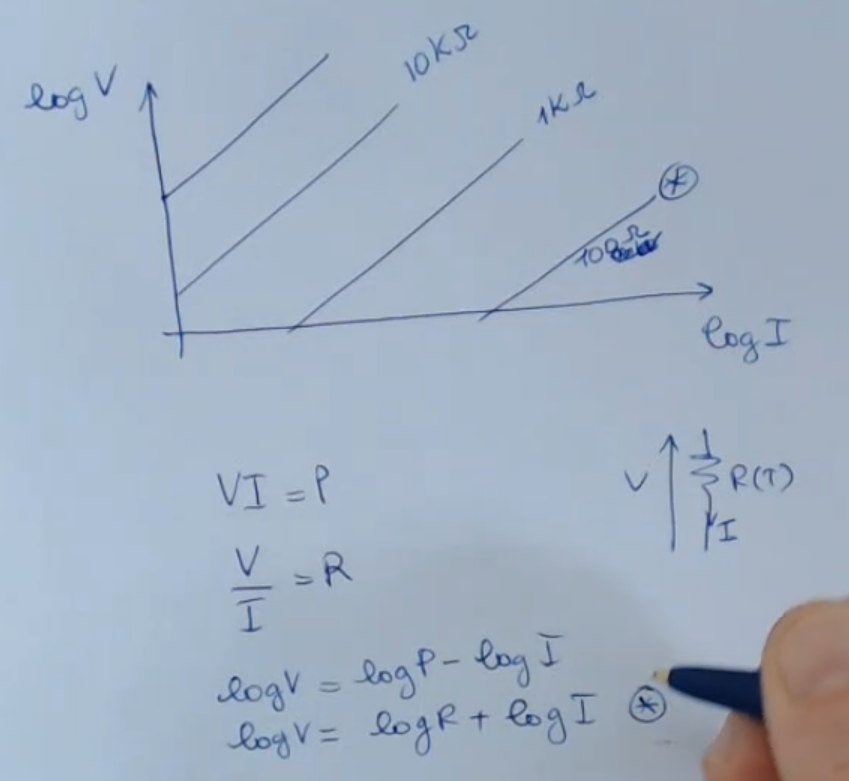
-
Formulas:And:
-
Visualize the effect of selh-heating on the measured resitance:
SaM - Coupling with the Environment (and Solution)
- Simple lumped thermal parameter system:
- Measured temperature at regime:Where:
- ==Solution==: If , then: .
- Graph:
| thermal conductivity () | Still Air | Glass | Gold | Diamond |
|---|---|---|---|---|
- Still Air means: “A porous material filled with Air”, so we are talking about only convection, no conduction.
- A bigger coefficient means a lower thermal resistance, so a better coupling, and a faster heat transfer.
So “still air” is an thermal insulator.
SaM - Electrical Noise
- Example:
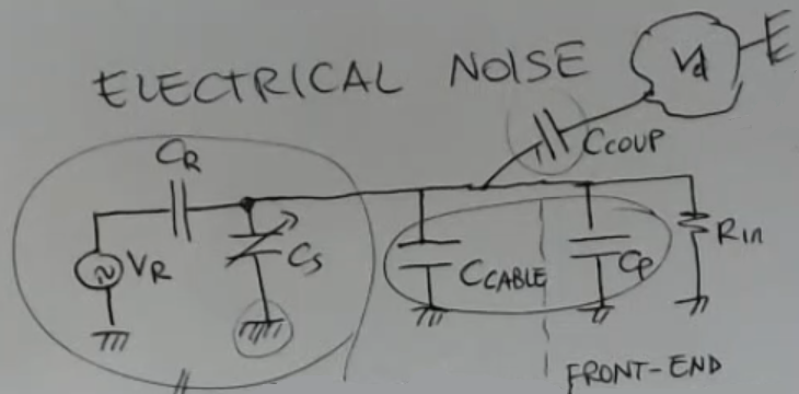
- Formula:
- Bode Plot:
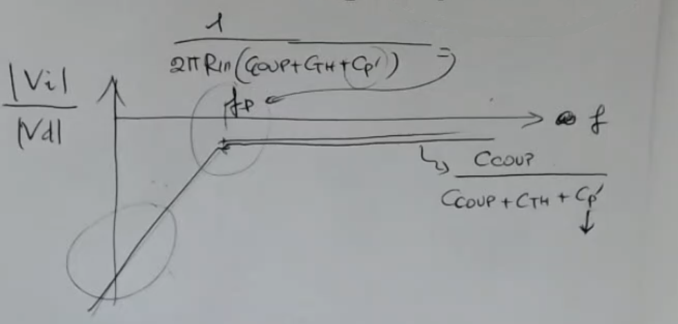
- At low frequency, meaning: , we can approximate as:
- Real World Measures:
- Especially in this case, if the resistance is small, the sensitivity of the circuit to electrical noise becomes smaller (a good thing).
⇒ ==It is better, if possible, to use a front end amplifier with low resistance==.
⇒ Meaning, that it’s better to use current, or charge amplifiers, so that we have the resistance very low, resulting in a cutoff frequency very high.
HOWEVER: we cannot choose a too-small input resistance, since if I put the resistance at , I don’t read anything . - It would be better to have the cutoff frequency much larger than .
Since the most important source of electrical noise is the power line wiring, that we have everywhere, and the power lines generate noise at . (“White Noise”)
- Especially in this case, if the resistance is small, the sensitivity of the circuit to electrical noise becomes smaller (a good thing).
- Terminology:
- : reference voltage.
- : reference capacitance.
In other cases you can have no reference capacitance, for instance if you measure humidity. - : sensor.
- : in case of a long cable, i need to consider it.
- : parasitic capacitance with external electric potential .
This could be for instance another appliance, or a person which moves. - : input resistance to front-end electroncis.
- : parasitic capacitance (from the front-end electronics).
- We can consider:
SaM - Shields
- Simple shield structure:
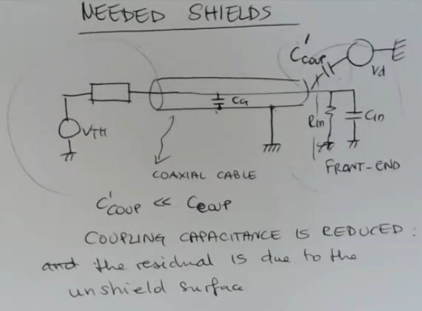
- Inside the closed metallic surface (“shield”), the electrical field is zero, due to the high mobility of charges.
- Shields are especially useful when I can’t use a current amplifier.
- The new is much smaller then the un-shielded .
- HOWEVER: the output still depends on .NOT_SURE_ABOUT_THIS
SaM - Coaxial Cable
- Structure:
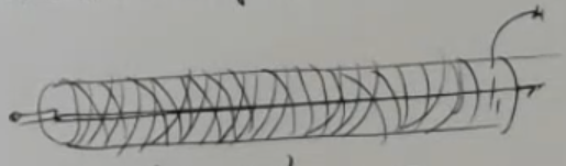
- **Inner Conductor or Wire.
- 1st Insulation.
- Outer Conductor or Elettromagnetic Shield.
- 2nd Insulation.
- Outer Jacket or Durable Shield (in particular this shield provides mechanical protection and shields the cable from environmental factors like moisture and physical damage).
- Electrical model:
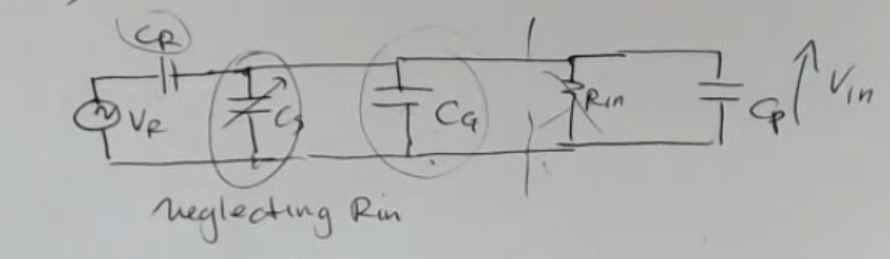
- Formula:
- Real World Measures:
- For a coaxial cable, we can imagine to have a value of capacitance , which is multiplied by the length of the cable.
So if the the cable is long and is really big, it will “mask” the relativily small value of our sensor ().
⇒ We will lose a lot of sensitivity. - A coaxial cable is not good if the sensor’s capacitance is small and if the cable is long ⇒ so if .
- ~Ex.: meters of cable means , we have said that our in in the order of , so ().
⇒ is times larger than the capacitance of the sensor .
- For a coaxial cable, we can imagine to have a value of capacitance , which is multiplied by the length of the cable.
- Terminology:
- : guard gapacitance, which in this case is the cable capacitance.
- : reference capacitance.
- : sensor.
- : input resistance to front-end electroncis.
- : parasitic capacitance (from the front-end electronics).
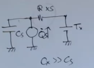
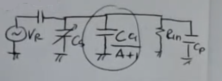
SaM - Driven Shields or Tri-Axial Cable
- Structure:
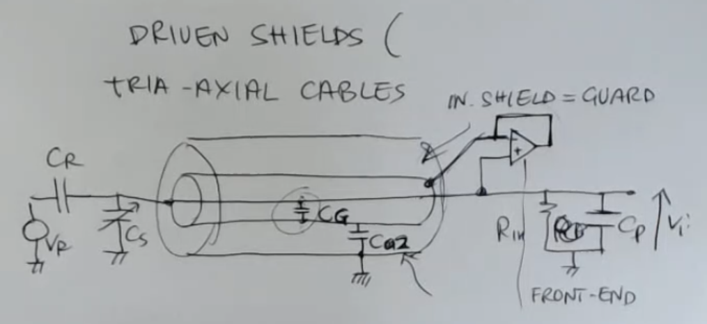
- An internal shield called guard that surrounds the wire.
- An external shield which is usually grounded.
- In this types of cables the guard is kept at the same voltage as the wire.
- Electrical model:
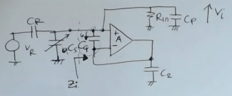
- Impedance seen by the sensor :
- Equivalent electrical circuit:
- Real World Measures:
- I will need an amplifier which has a large gain, to reduce the impedace , and a wide band, since we are operating at AC, so it has to use large frequency because of the small value of the capacitance of the sensor ().
Usually the operating range (depending on the value of the sensor) is .
⇒ So we need this open loop gain to be or , at around . - The last thing we need, since we have a variable signal, is a filter to remove the drifts at low frequency
- I will need an amplifier which has a large gain, to reduce the impedace , and a wide band, since we are operating at AC, so it has to use large frequency because of the small value of the capacitance of the sensor ().
- Terminology:
- : Guard capacitance between wire and internal shield.
Tho since wire and internal shields are at the same voltage, this capacitance is empty of charge, so the special property of tri-axial cables is that: - : Second shield capacitance, this has charge, so its value is different from .
- : Guard capacitance between wire and internal shield.
SaM - Tri-axial Cable + Tri-axial Sensor
- Normal capacitive proximity sensor and a tri-axial sensor:
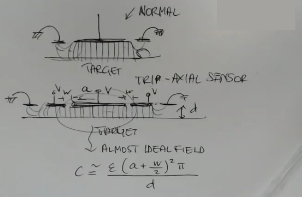
- The field in the normal sensor, is bend at the edges, instead for a tri-axial sensor that is not the case, we consider the field as “almost ideal”.
- In the tri-axial sensor, the “guard system”, prevents the distortion of the field due to something outside the sensing area.