Remeber:
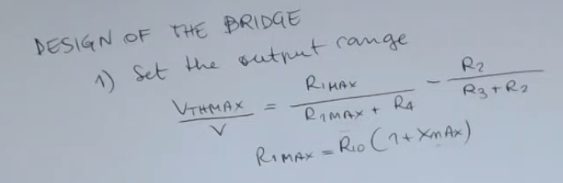
Set the output range , from this find .
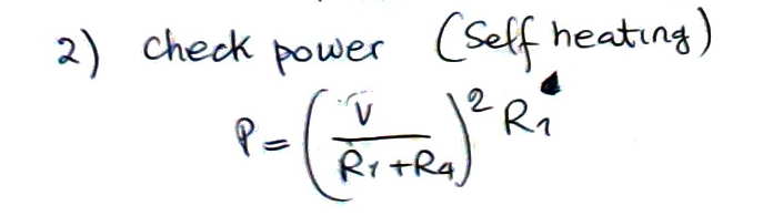
Check the power (self heating):
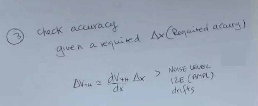
Check accuracy or maximum error:
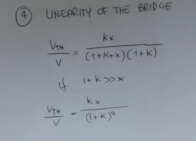
Linearity of the bridge: so if .
The non-linearity error:So assert that:
Follow this 3 steps:
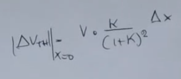
And if we measure it in a certain condition, which is around , it will give us this expression here:
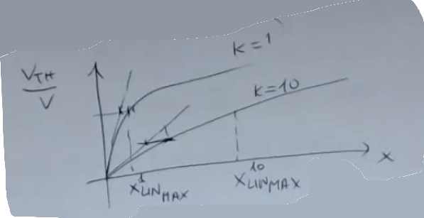
So in fact, if I draw what happens here, I will have this: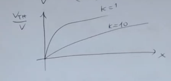
- Different lines correspond to different values of .
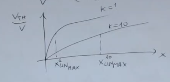
==I will have an , which stands for the maximum value for (given a certain ), under which we are in the linear region==.
So for me, “ideal linear” is a circuit where I would have exactly this output here: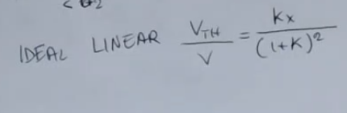
- Not as an approximation, but as a real output.
Then I evaluate the non-linearity in this way: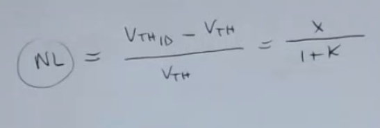
Where:
- is the linear approximation we make when we are in the linear region (straigth lines), and we can write:
- is the real line:
- So we have that the (non-linear error) is equal to:
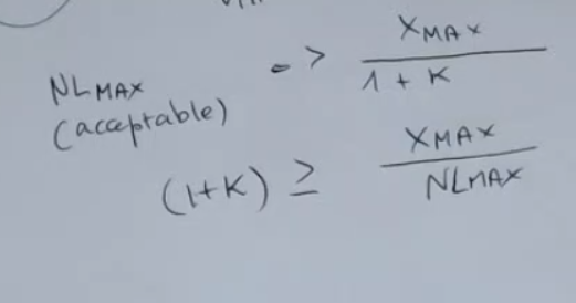
- Given your maximum value of , so the range of your measurement of our sensor (), you will find the right value for .
For instance, if I have as possible acceptable non-linearity, then I will have that key has to be approximately multiplied by the maximum value of , which is your measurement range: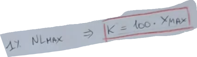
The last point of the design of the bridge is point 5. Optimizing the Relative Sensitivity of the Bridge:
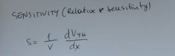
- Remember: : “deviation output of the sensor”
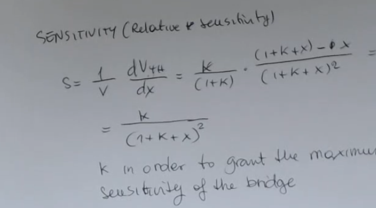
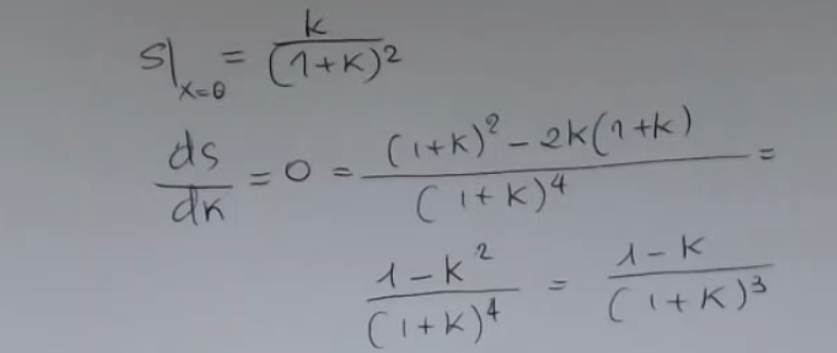
This means that the maximum sensitivity it’s reached if :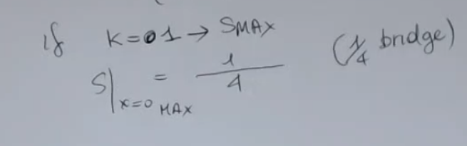
So this means that you optimize the bridge for the point of view of the sensitivity is the one in which all the resistances have the same value: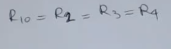
- They have to be all the same value because we also have considered this bridge a balanced bridge, so:
And obviously if you select this value for (), you have that maybe the condition for linearity, which is this one: Maybe it’s not fulfilled.
- Remember the actual condition for linearity (where we consider a small non-linearity maximum error ) is:In this particular case we considered an enormous error that means that if the real value is than the output value of the sensor is , way too much.
Usually we consider
And so linearity requires large value of unless is very small, like in the strain gauge, instead == is the condition for the maximum sensitivity==: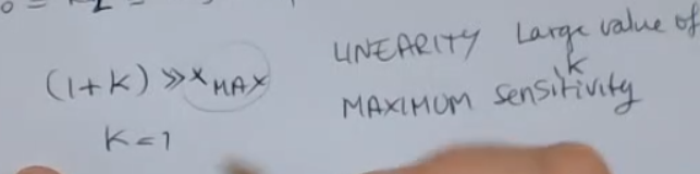
- So for Strain Gauges, where the value is really smallere than one, then you can select this value and obtain also a linear bridge and everything is okay.
- For RTD, where the value may be large, then you can’t usually take this value for the design of the bridge, you have to take into account first of all the linearity because linear behavior you know is a very good quality for a circuit because it makes it simple and allows for having very good model of its behavior.