Remeber:
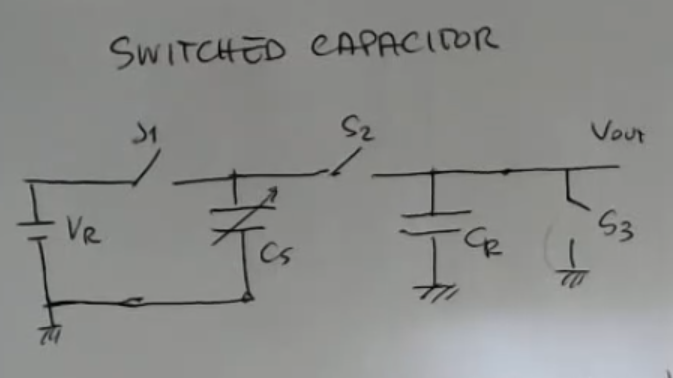
A switched capacitor can be used for increasing the capacitance value, with respect to the sensor’s capacitance, without changing the actual capacitance.
This is like amplifying the capacitors of the sensor:
- So the starting phase, : closed, so that we start from .
- Then there is a sequence of repeated steps, which are this ones:
- : ON, : OFF, : OFF.
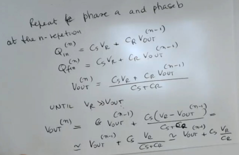
So in this phase, we have a charge, which is stored in the capacitance , equal to:
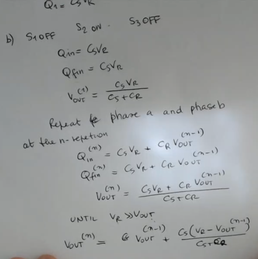
So we have this charge stored in at this point.- : OFF, : ON, : OFF.
At the beginning of this phase, we had the initial charge in .
While at the end the total charge reamins the same, it is now shared between and , so has given some charge to .
So the value increases.- So then we go back to the first phase (1.), so: : ON, : OFF, : OFF.
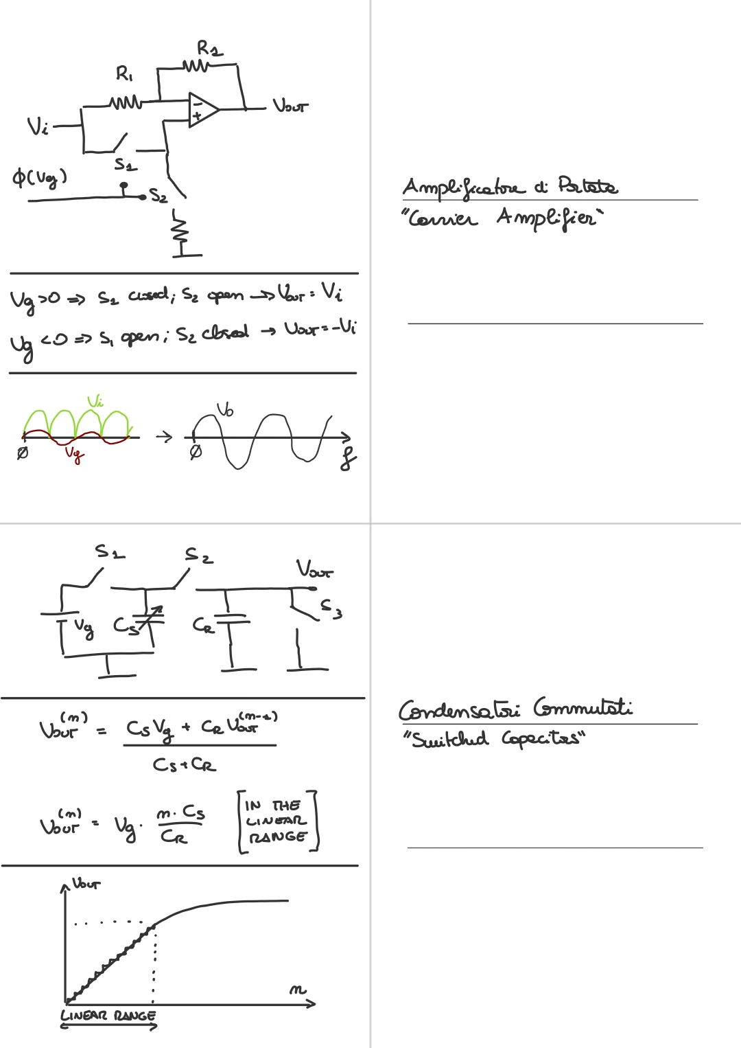
Most important formula: After steps we have that:Where: So to obtain the sensor’s capacitance we just use this formula:
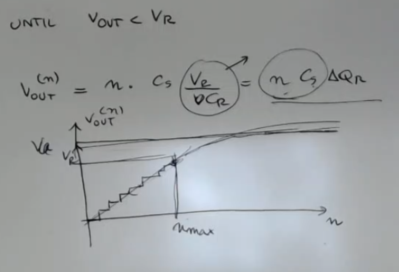
If I perform all the calculations, I put the steps in a graph, I will have this:
- is a constant term, which I call .
- So we have a linear behavior at the beginning, and then saturation, because we can go beyond this value, we will have a saturation at a certain point, the steps will become smaller and smaller until I reach the full charge of the capacitance.
==That’s why I can perform this “cheat” only untill the voltage ==.
⇒ If I limit the measurement ratio to , opprotunaly choosen, I will remain in the linear range of the capacitance, and I have this very simple way of amplifying the signal due to the sensor.
Memory Card
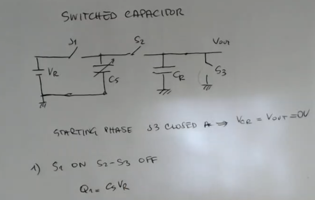
- So the starting phase, : closed, so that we start from .
- Then there is a sequence of repeated steps, which are this ones:
- : ON, : OFF, : OFF.
So in this phase, we have a charge, which is stored in the capacitance , equal to:
So we have this charge stored in at this point. - : OFF, : ON, : OFF.
At the beginning of this phase, we had the initial charge in , which was:
And the charge at the end is the same obviously the same:
But the voltage, since these two are put in parallel, at the end of this first phase, will be:
So we have a first step of , the output voltage, which is given by this value here. - So then we go back to the first phase (1.), so: : ON, : OFF, : OFF.
- : ON, : OFF, : OFF.
After repetitions, we will have:
This is like having a larger capacitance, with respect to the sensor’s capacitance.
This is like amplifying the capacitors of the sensor, and actually, if I perform all the calculations here, I put the steps, I will have this:
- is a constant term, which I call .
- So we have a linear behavior at the beginning, and then saturation, because we can go beyond this value, we will have a saturation at a certain point, the steps will become smaller and smaller until I reach the full charge of the capacitance.
That’s why I can perform this “cheat” only untill the voltage . - If I limit the measurement ratio to , opprotunaly choosen, I will remain in the linear range of the capacitance, and I have this very simple way of amplifying the signal due to the sensor.
- Moreover, the readout circuit, when it reads the voltage output, sees these capacitors that can be very large.
⇒ I don’t put the wiring in parallel to a small capacitance (less restrictions). - Obviously, here I didn’t take into account the parasitic resistances, and I also considered all the switches ideal, and so this is something which is really simplified, but it any case the principle is this.
- Thing to remember:
- Most important formula:
- After steps we have that:Where:
- So to obtain the sensor’s capacity we just use this formula: