Remeber:
To understand this circuit you need to rememebr:
- How current mirror is made.
- The BJT formula (in active region).
Also let’s see how many BJT in parallel behave, this is the circuit:
The current , will be the sum of all the currents of each parallel BJT.
we consisder them equal and define the currents of each parallel BJT as "", so we have:This is like having a more conducting device, where the current is times the current of the single the basic device, so if we use the BJT formula, we can say:
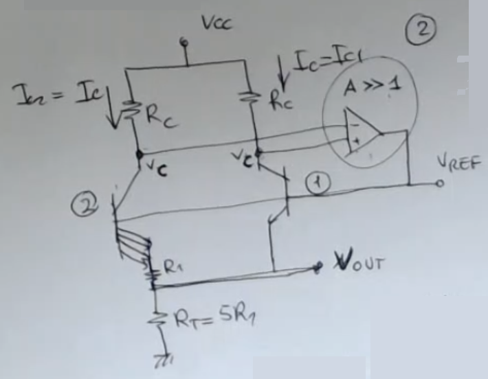
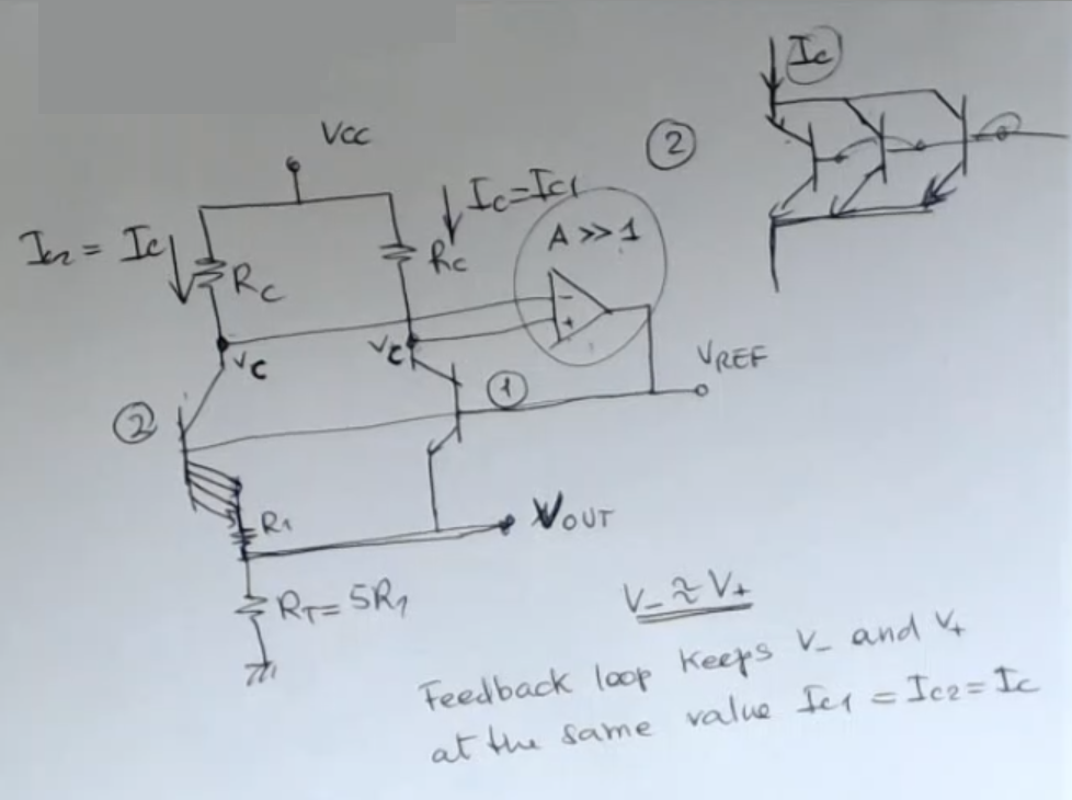
This is the strucuture of a “classical band gap based temperature sensor”:
- We have a differential structure with two identical resistances, and two different BJT.
- The 2nd BJT is the strucutre we have seen before with parallel BJT.
- The bases of the BJT (1) and (2) are at the same voltage, and the circuit here is concluded with a feedback loop.
- This is an amplifier which has a very high gain.
⇒ Therefore these two voltages, and are approximately at the same value.- So (1) and (2) have also the the same collector voltage.
- Since the two resistances are nominally identical we have the same current in these two branches here ().
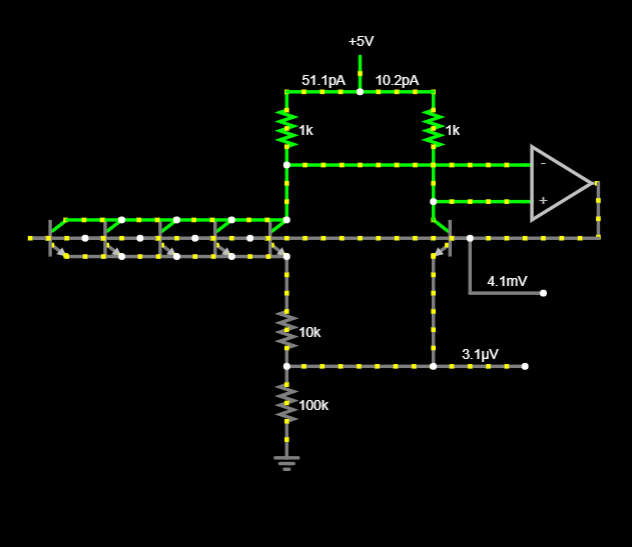
- Here’s a circuit. (Circuit at rest , BjTs NOT in active region):
- Her’s another circuit (Go to one of the BjT in the circuit
>>Double click it>>“Edit Model”>>Change the value of the “Saturation Current”, and see how the output voltage change.)
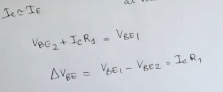
Here’s it with each BjT at , and they are in active region:
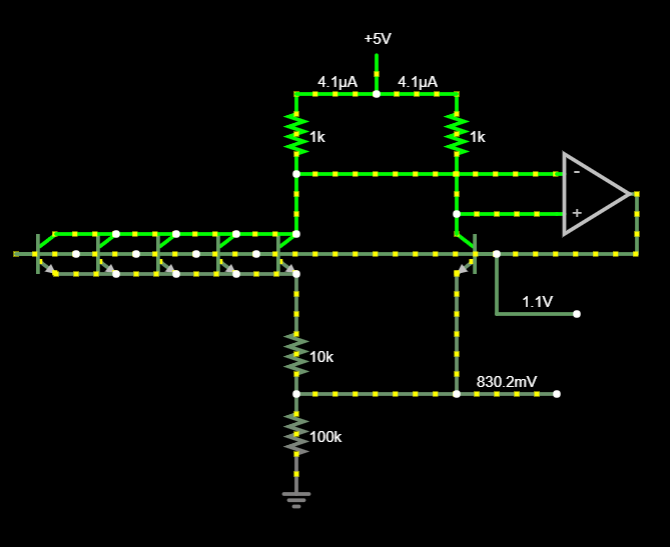
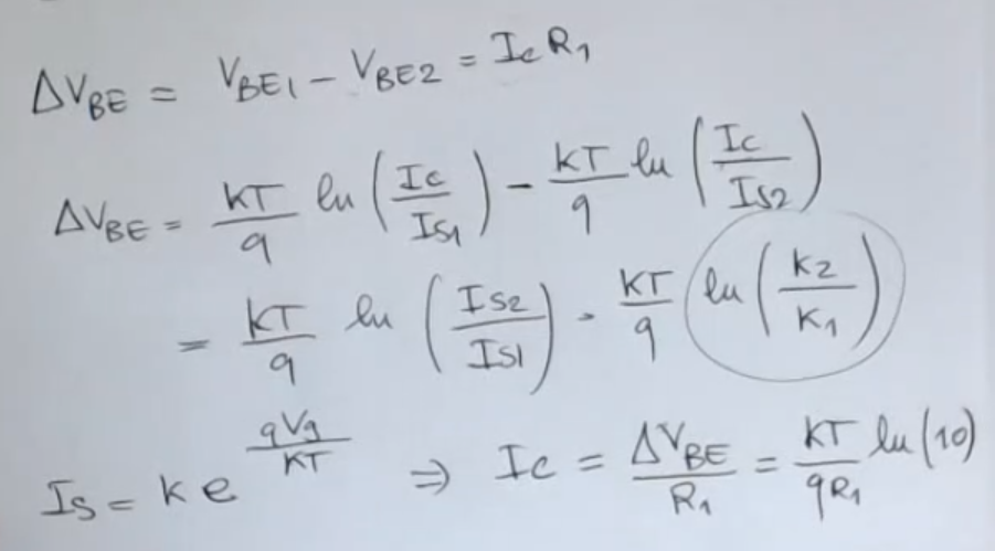
Because you know that both BJT are in the active region ⇒ we can neglect the base current, so . So now we can relate the current to this voltage :And since we know that a BJT in active region has this formula:And the property of logaritms , we can say:We simplify:Note that the ratio between and is equal to , we can also say that:
We know that:
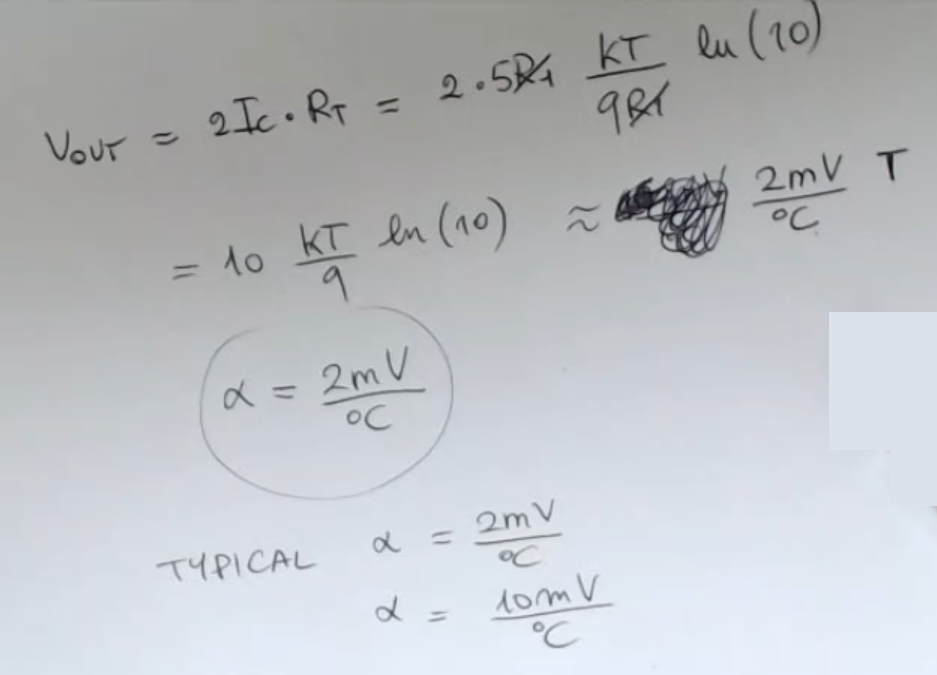
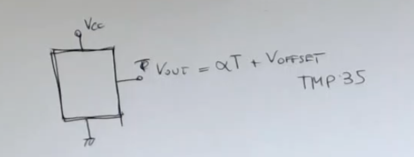
So:And we can finally calculate the function of this sensor:IMPORTANTE It has a linear dependance on temperature.
The usual values for the sensitivity for this kind of devices are in the range:IMPORTANTE
So this device that we have here, we have discussed is a device with three pins:
- In the theory we have found no offset, but in reality there could be one.
- So this is a 3 pin device, but there also exists other circuits based on the same philosophy and the same topology or similar topology which instead have 2 pins.
Memory Card
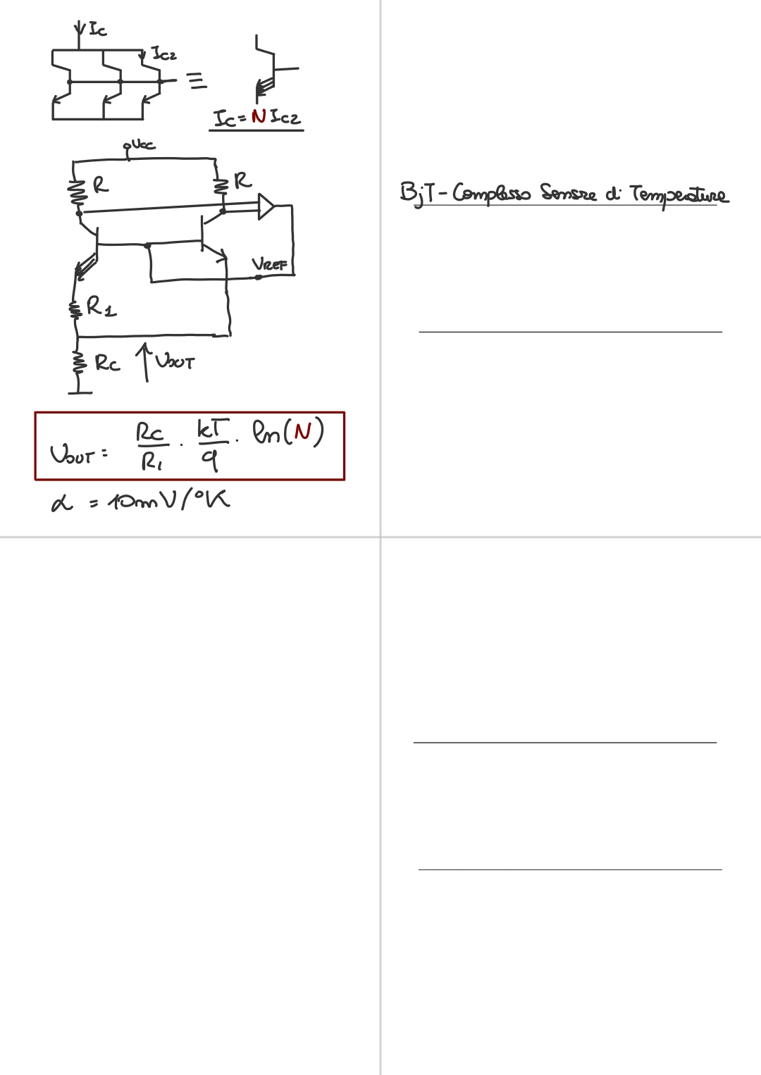
This is the structure that can be used also to obtain regulated voltages where the temperature dependence is compensated (or eliminated).
- We have a differential structure with two identical resistances, and two different BJT.
- The 2nd BJT can be seen more clearly (how it is strucutered) on the right.
it’s like having many BJT in parallel.
⇒ This means that the current here , will be the sum of all these currents, of each parallel BJT.
This is like having a more conducting device, where the current is times the current of the single the basic device. - The bases of the BJT (1) and (2) are at the same voltage, and the circuit here is concluded with a feedback loop.
- This is an amplifier which has a very high gain.
⇒ Therefore these two voltages, and are approximately at the same value. - So (1) and (2) have also the the same collector voltage.
- Since the two resistances are nominally identical we have the same current in these two branches here ().
Because you know that both BJT are in the active region ⇒ we can neglect the base current, so .
So now we can relate the current to this voltage :
And so we have the output voltage here:
- We use the property of logarithms:
- So we have:
- We can simplify and obtain:
- Where there ratio between and is equal to .
- So finally:
- We have supposed that the ratio but this depend on the structure, since we have that:Then we wil have that since both are equal and is the sum of identical collector currents (since the 2nd BJT is the parallel of many BJT):
- So finally we have: There must be an error somewhere becouse in this case the output comes out as negative with respect to what there is written in the notes, since:
This is not a big problem, but it is different.
- So in this particular example we have supposed , so the BJT (2) is composed of 10 stacked BJT.
- NOTE: If we choose to stack only 1 BJT, so , we have that so we need at least BJT in parallel in position (2), to have a reading.
- So now has a linear realtionship with temperature, really good, this means that is also has a fixed sensitivity .
- NOTE: We have supposed a independent on temperature.
So this device that we have here, we have discussed is a device with three pins.
- In the theory we have found no offset, but in reality there could be one.
- So this is a 3 pin device, but there also exists other circuits based on the same philosophy and the same topology or similar topology which instead have 2 pins.