Remeber:
This is the complete circuit for amplitude modulation with differential capcitance sensors:
- So differential because the capacitances are:
- is needed to reduce the effects of DC errors of the amplifier.
- Let’s explain each stage:
- We have a first conversion of the quantity into a capacitance, done by the sensors and , both sensors are differential sensors, and we suppose them to be the same type of sensors, only mounted in “opposite directions”.
- Then we have a first stage formed by a generator of AC voltage () and an oscillator ().
In this stage we convert the capacitance (of the sensors and ) into the amplitude, that means that we scale the amplitude of the sine generated by by the capacitance of the sensors, and we mantain the same frequency.
In this particular example we have taken the phase of the sine signal () at a fixed frequency ().
The formula at this stage is:- This last part here, formed by the carrier amplifier followed by the Low Pass Filter (LPF), is needed to recover the amplitude and the phase, specifically with the carrier amplifier we recover the phase, (the output will be positive if and have the same sign, or negative otherwise) and with the low pass filter we will obtain a DC output that depends on the sensors’ capacitances.
So at the end, we can have a low frequency voltage, which follows .
So the output () is ready to be, for instance, acquired by an AC-DC (Analog to Digital Converter).
- The output of the second part (before the carrier amplifier), has this form:
- is the lower frequency limit, defined by the feedback impedance, our frequency must be higher than this.
- I put in the formula, because I’m dealing with the module, I can’t tell just by looking at the output if is positive or negative.
==And this is the reason why we need the carrier amplifier, since we lose the sing of ==.
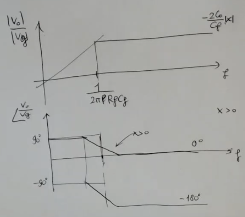
- is the cutoff frequency.
- I can put in the formula, because I’m dealing with the module.
- If larger than , then it means that I start from a positive phase, , then I go to a phase.
- Instead, if, so this is smaller than , so if I have negative, obviously I start from , then I go to .
So what happens?
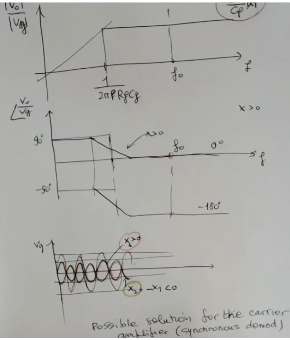
- No matter the sign of the output will be the same, so it depends on .
⇒ I need to recover the phase for the sign of . - To recover the phase, I need the reference signal ().
⇒ So I need a circuit able to compare the phase of the input signal with the phase of the output signal, in order to understand if they are in phase or out of phase.
There are many solution for this problem, ==we have seen the low frequency solution==: the Carrier Amplifier: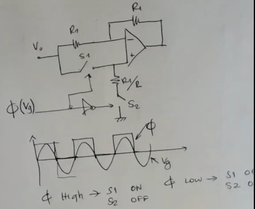
- This amplifier changes the sign of the input signal , based on the sign of the signal , so we will obtain as output signal
Complete AM Circuit: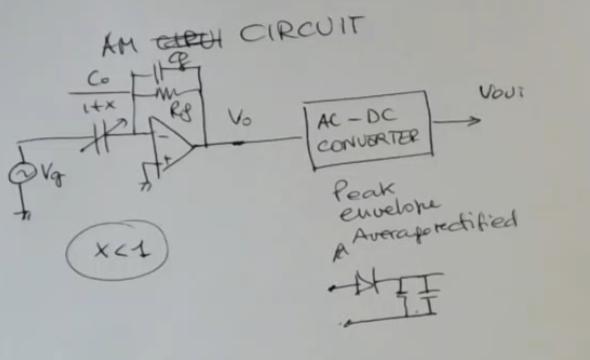
- NOTE: This is the first circuit we have seen, where the ouptut is dependent on instead of
- Since we have supposed to have and not just , then cannot get negative and we don’t need any more circuitry, of course if (acceptable conditionNOT_SURE_ABOUT_THIS )
- In case we don’t have the in the formula, and can get negative, we need all the information related to the amplitude, and the information related to the phase.
Otherwise the simple initial system here is fine. - If I want to have a better (larger) dynamic of the output I can correct the (which is fixed, so it doesn’t carry information), and in this case can go below and I need the previous circuit as well to recover the sign.
- At the end we can see a simple AC-DC Converter (Alternating Current to Direct Current Converter) (a “peak” or “envelope”, or “average rectified”) circuit.
Circuit :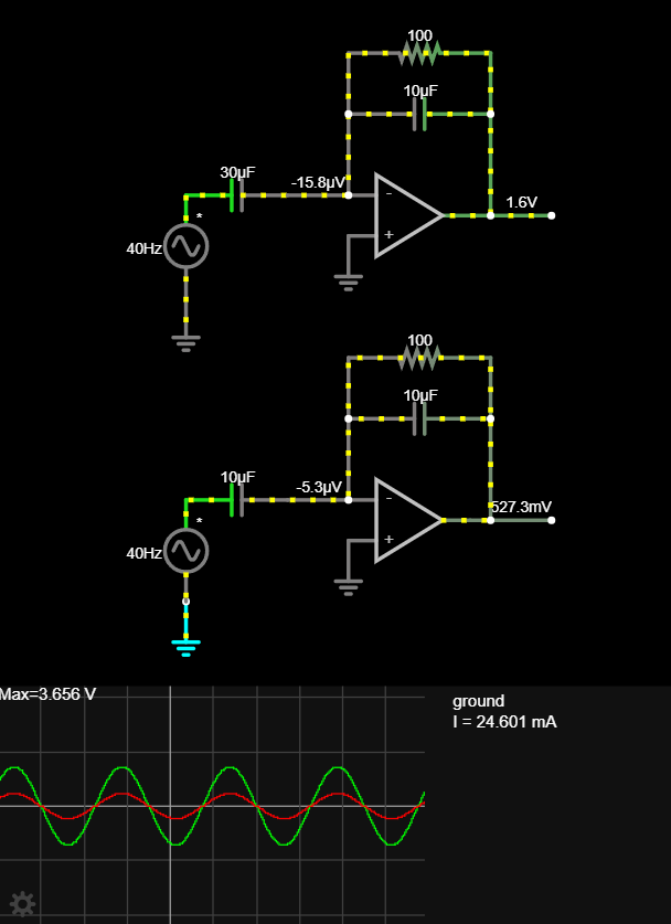
- Here is a simple circuit and as se can see if we change the value of the capacitance of the sensor, we are moduling the amplitude of the output, while the phase is decided by the AC voltage source ()
So we summarize what we have seen when analyzing the complete circuit for amplitude modulation: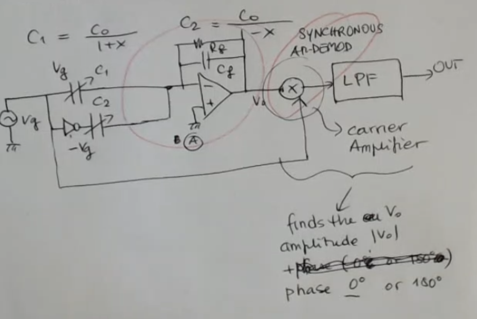
- We have a first conversion of the quantity into a capacitance, and this is the sensor here, in this case differential.
- Then we have a first stage including this, which is an oscillator, a generator of AC voltage, and with this stage here, we convert the capacitance into the amplitude, and the phase in this case, of the sine signal at a fixed frequency .
- This last part here, is needed to recover the amplitude and the phase.
- So at the end, we can have here a voltage, a low frequency voltage, which follows , and so it is ready to be, for instance, acquired by an AD (Analog to Digital Converter).