List of things to memorize:
SaM - RTD Sensor
Link to original
- SaM - Definition of RTD Sensors • Resistive Temperatrure Detector Sensors • TCR (Temperature Coefficient of Resitance)
- SaM - Calendar Van Dusen Equation
- SaM ~ Real World Example • Standard RTD Sensor • PT100 Sensor
- SaM - Accuracy of the Complete Measurement System
- SaM - Remove the Offset in the Measurement System
- SaM - RTD Example • Linearized Uncertainty
- SaM ~ Solution Based on a Resistive Bridge and an RTD (Skipped)
SaM - Definition of RTD Sensors • Resistive Temperatrure Detector Sensors • TCR (Temperature Coefficient of Resitance)
- RTD (Resistance Temperature Detectors)
- TCR (Temperature Coefficient of Resistance) formula:
- PTC: Positive Temperature Coefficent ().
- NTC: Negative Temperature Coefficent ().
- TCR Definition for RTDs:
- Real World Measure:
- The usual sensitivity of these sensors is:
- We have seen two tyes of RTDs:
- Thin Films:
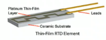
- Wirewound:
- Thin Films:
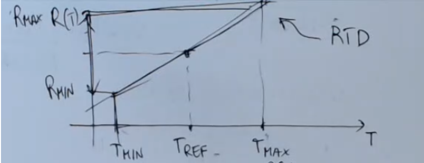
- Terminology:
- is the resistance the sensor assumes at .
- is the resistance the sensor assumes at .
SaM - Calendar Van Dusen Equation
- Formula:
- Simplified formula:
- More accurate sensitivity:
- Find the maximum error for using the Calendar Van Dusen Equation:
- Define the formula : :
- Find the inverse formula .
- Find the maximum error in the Worst Case (WC) possible:Where:
- is the maximum measurement error and depends on the circuit used, not just on the sensor, so we forget about it.
- are the maxium possible variations, since we took the worst case possible.
- Real World Measure:
- For the PT100 sensor:
- , or: .
- For “Class A Devices” the maximum error is .
- For the PT100 sensor:
SaM ~ Real World Example • Standard RTD Sensor • PT100 Sensor
- This RTD sensor is made of platinum, it is a standard material very stable, reproducible and resist to oxidation
- It is called PT100 since:
- It is made of platinum, “PT” stands for Platinum.
- Its nominal resistance value assumed at is .
- Calendar Van Dusen coefficients:
- Self-heating effect: .
- Usual temperature range of these sensors: .
⇒ Usual resistance value range: .
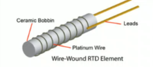
SaM - Accuracy of the Complete Measurement System
- Complete Measurement system:
- Simple example using the PT100 sensor:
- Accuracy of the complete system:Where:
- : nominal resistance of the PT100 sensor.
- : Calendar Van Dusen coefficient.
- : open loop gain of the operational amplifier.
- : current source.
A higher current improves the SNR (Signal to Noise Ratio), however it can create a self-heating problem.
SaM - Remove the Offset in the Measurement System
- Linear sensor (~Ex.: RTD) equation, taken within :
- Simplest read-out electronics:
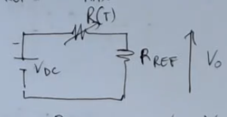
- Output formula:
- Output graph:
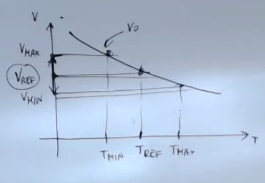
- Formulas:Where:
- is taken as .
- can be seen as the offset of the system.
- While is its dynamic range.
- The information given by the sensor lies all in this small range that we will call .
- Problem: we don’t fully utlize the range given by the acquisition system (A/D).
Solution: compensate the offset, so bring the output signal to have a :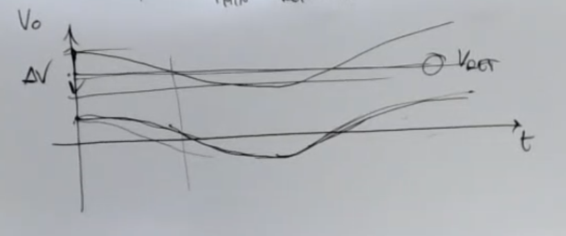
- Using a balanced bridge:
- Problem: we might need to consider the wires resistances.
- Problem: we have corrected the offset, but we cannot correct the drift, which is usually taken as:
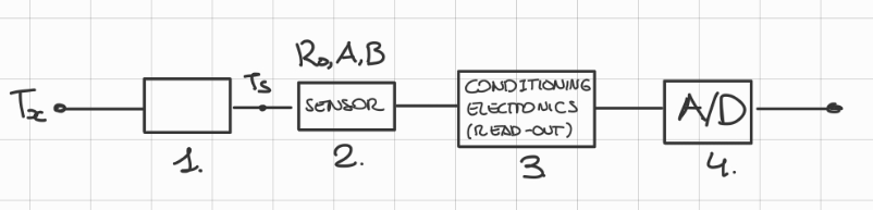
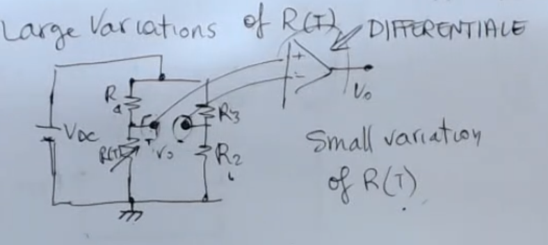
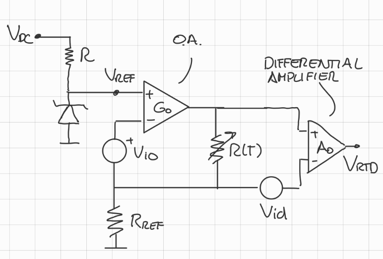
SaM - RTD Example • Linearized Uncertainty
- Circuit:
- Output formula:
- The complete formula for this RTD circuit depends on:
- Uncertanty formula:
- Uncertanty simplified:
- Terminology:
- : open loop gain of the differential amplifier.
- : voltage input offset.
- : output of the operational amplifier .
- : open loop gain of the operational amplifier.
- : RTD sensor.
- : “drift of the reference voltage”.
- : “drift offset” for the PT100 it is about .IMPORTANTE
- : “drift offset”.
- or : “Voltage at the Least Significant Bit”.
SaM ~ Solution Based on a Resistive Bridge and an RTD
(Skipped)