Remeber:
Circuit:
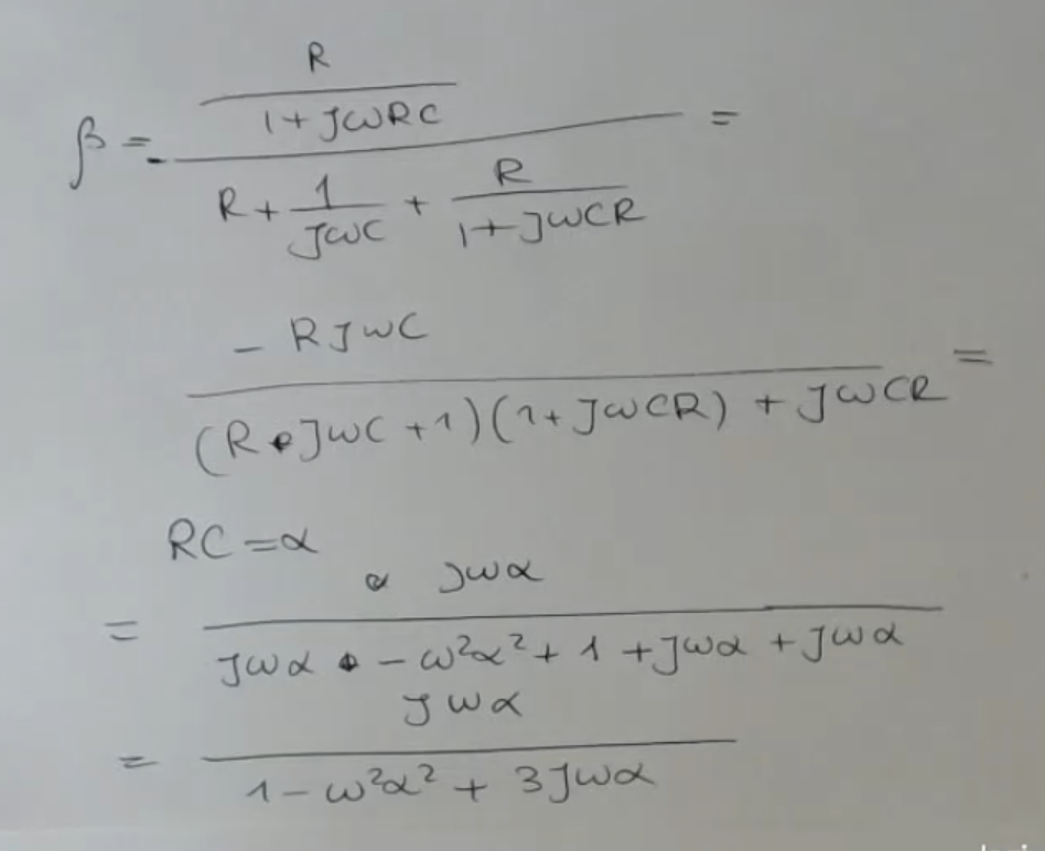
- Feedback coefficient:Where:
- If we enforce , we will have that is a real negative number, so we will have the second Barkhausen condition already satisfied.
- Finally if we take:We will have also: , and consequently:
And with that all the Barkhause conditions are satisfied, and the system will oscillate.
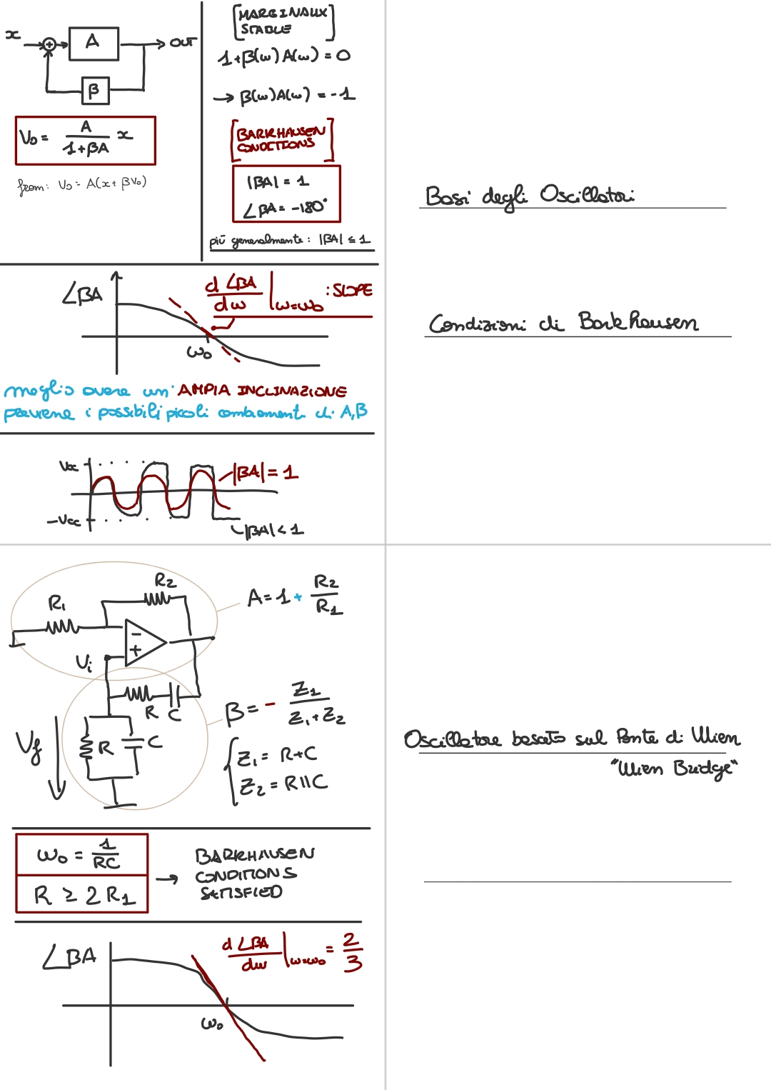
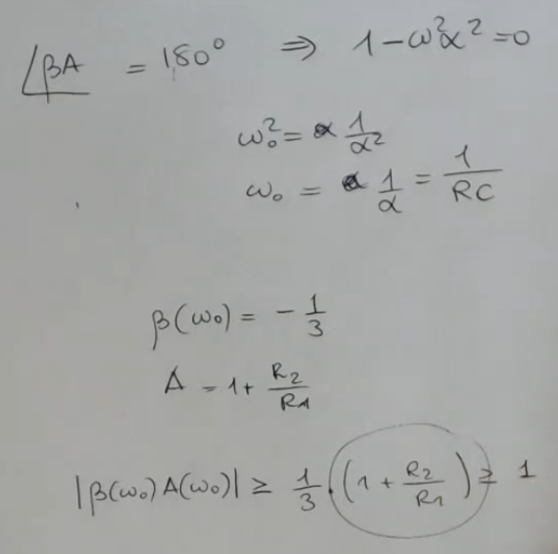
Another way of seeing things: Then we apply the Barkhausen conditions, so that our oscillator does in fact oscillates, and we find:
- , where: .
- .
- We drow the plot:
- Oscillators based on Wien Bridge have a constant slope around :
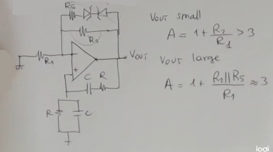
We have also seen another variation of an oscillators based on the Wien Bridge:
- This kind of circuit ensures to reduce the distortion due to an unstable behavior of the circuit.
- Here are some circuits comparisons:
- Remeber that:
- If we take the output will be a sinisuidal function.
- Instead for the output will diverge. (this is the “unstable behaviour” we refer to)
Memory Card
I will show you two different kind of oscillators, sine wave oscillators, one, which is meant for low frequency and the other one, instead, which is suitable for high frequency applications
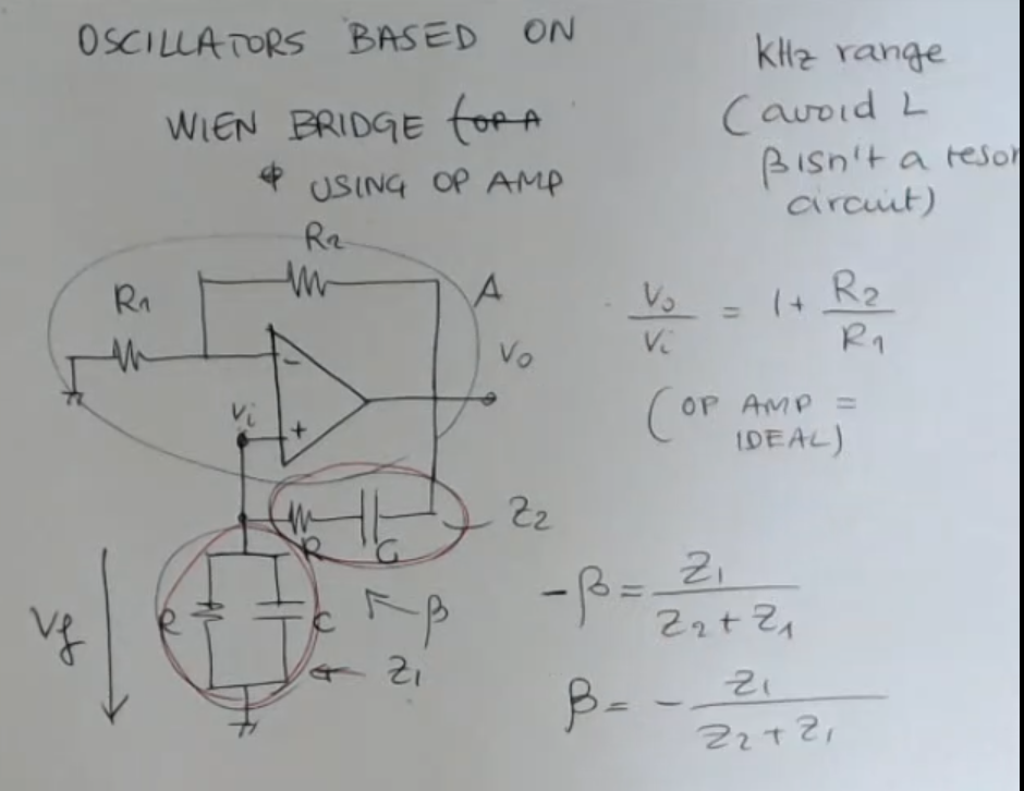
- NOTE: To find we need first to detach the positive feedback loop.
- Circuit
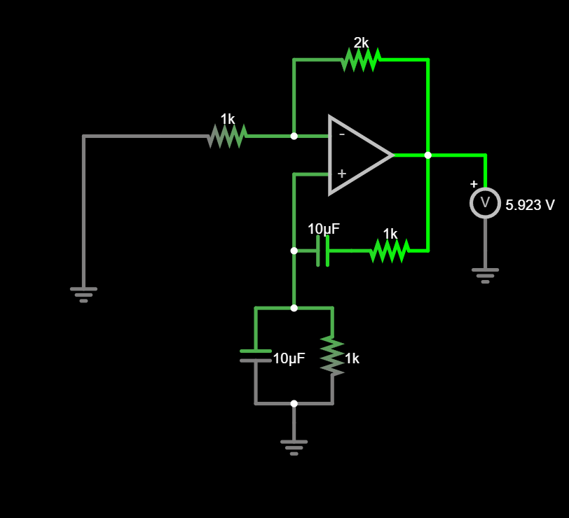
NOTE:- In this circuit there is no , this is an ideal oscillator, so it is designed to relay on no exitation (exept the power given to the amplifier by )
- The “initial power”, that makes the ciruit work is stored in one of the capacitors, i’ve set and .
- In reality a DC voltage exatation is needed, at first to start the circuit and then we’ll need to mantain it (small exatation need at the input), since some power will be lost for non-ideality reasons.
- Online Source: Youtube
- We define our positive feedback coefficient as .
- In this case we also have an arbitrary negtive feedback coefficient: .
I call it arbitrary beacause usually it is defiened as just the gain of the amplifier . - So as it stands the only way for the circuit to oscillate is that
- Also remember that we need the product to be a real negative number, such that .
So we have found (in the note the sign disappears at the end): Where:
- .
Remember the “feedback loop formula” is:Starting from this formula we have seen the two Barkhausen conditions:
So if we enforce , we will have that is a real negative number, so:
- Now we need the positive feedback loop coefficient to be greater than the negative feedback loop, so the positive feedback loop is: , and we must meet the condition: .
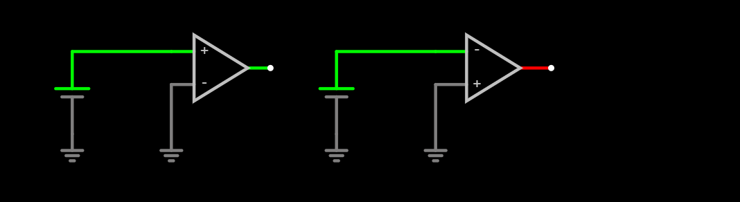
NOTE this is equivalent to the second “Barkhausen condition”: - Positive Feed Back Loop Example
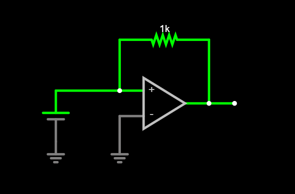
- Positive Feed Back Loop Example (2)
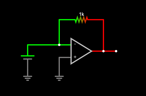
- Notice how the sign of the AO changes the sign of the oputput, but it does not mean that the feedback loop at the is a positive feedback loop and the one at the is a negative one, however oftein it is actually like this, but just thanks to the construction of the loop.
- Open Loop AO
So we have found:
We draw the plot: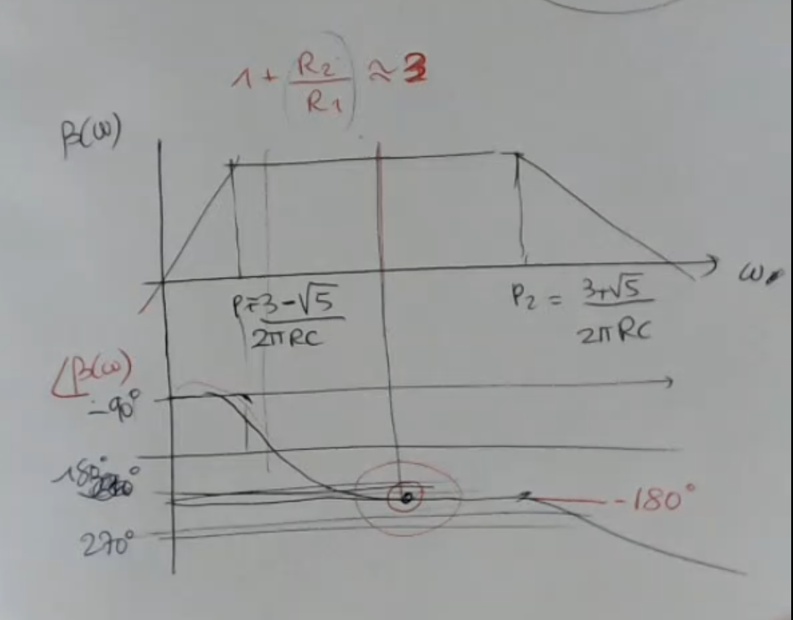
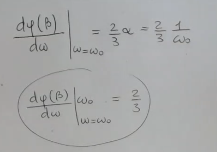
- We analize the “inclination/slope” of the phase of at , and we obtain this valueNOT_SURE_ABOUT_THIS
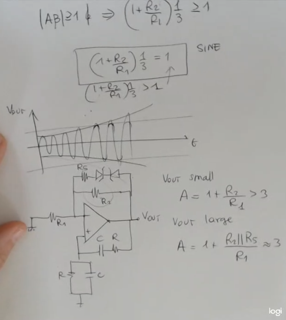
- If we take the output will be a sinisuidal function.
- Instead for the output will diverge.
- This kind of circuit ensures to reduce the distortion due to an unstable behavior of the circuit.
- Here are some circuits comparisons:
- So in this case the output get’s limited by the diodes, and if we take the value doesn’t change (much), so that the frequency remains the same, which is important.
- For small, it’s maybe approximately .