Remeber:
Formula used for transformers or magnetic induction:IMPORTANTE A transformer with mutual inductance and two currents and flowing trough its two “branches”, then we will have the two voltage drops equal to (in the frequency domain):\begin{align}&V_1 = j\kern2px \omega \kern1px M \kern1px i_2\\&V_2 = j\kern2px \omega \kern1px M \kern1px i_1\end{align}
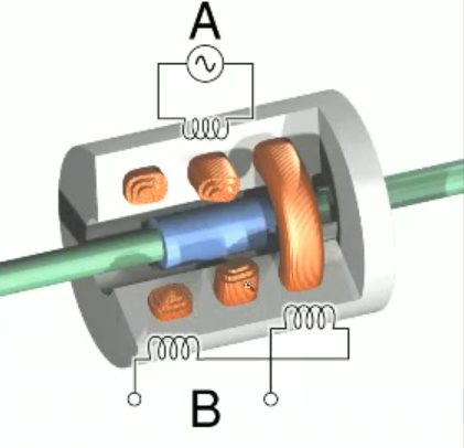
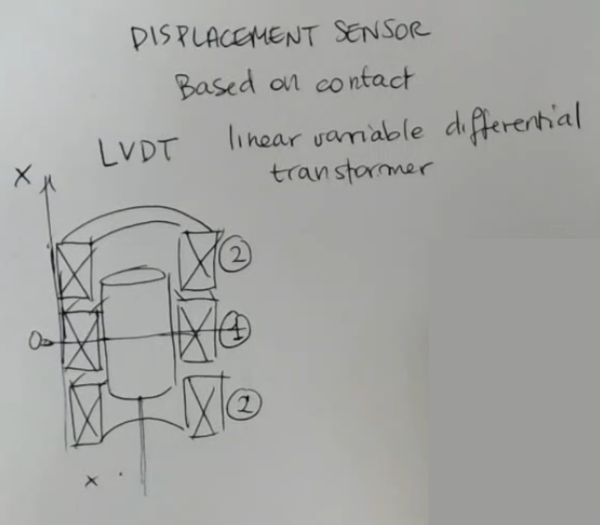
- Here is a scheme of an LVDT Sensor:
- The primary winding is the one here at center and two identical secondary windings at the opposite ends of the cylinder.
- The primary winding (or coil) here is excited by an AC voltage such that a magnetic field is created.
The inner cylinder called the core is ferromagnetic.- When the sensor is in its reference position, the core is perfectly centered and symmetrical with respect to the secondary windings.
⇒ The mutual inductance, between the primary and each secondary coils is exactly the same when the core is in its reference position, so the output will be .- If instead the core moves, then the structure becomes unbalanced and the mutual induction changes.
So one of the mutual induction between the primary and one of the secondary windings is increasing and the other is decreasing depending on the position of the core.
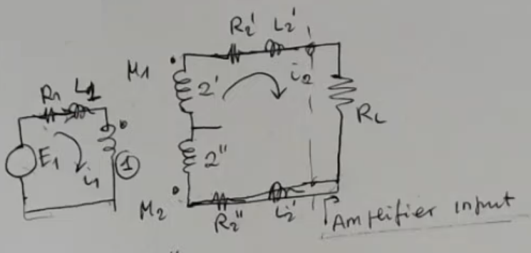
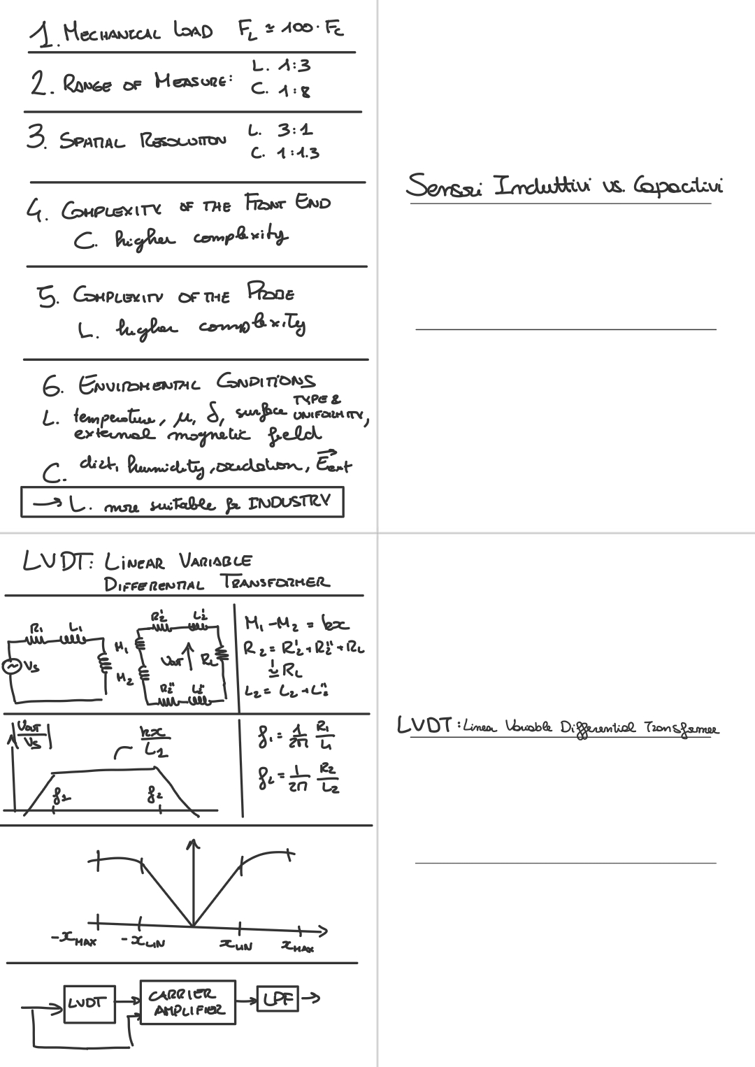
Here is the electric circuit:
- The output formula is: Where:
- (linear approximation).
- ==Remeber that this model is valid for ==, meaning that the mesurand must vary relatevely slowly to the exatitaion, so that we can consider constant to respect to the exatation signal .
Let’s look at the Bode plot of the transfer function :
- There is a zero in zero, and two poles one at and one at .
- If operate in “linear reagion” meaning with , and we suppose (as it usually is) , so that and we can approximate:Where, we defined:
It will be wise to select , so that the output will be in-phase () with the input, where:
What happens if ? ⇒ The initial phase is shifted by and the same is true for the phase at .
We will lose the sign of at the output. If we draw the output I find something like this:
- We can approximate this sensor as linear if we stay in the “linear range” defined by .
- But sometimes it is accepted to work in the extended range.
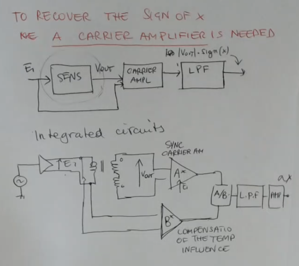
To recover the sign of we need a carrier amplifier:
- Remeber that the exation is an AC signal, and as we have seen that after a carrier amplifier, there is a need of a LPF (Low Pass Filter), which gives us finally a DC signal.
- The final outptut will be the amplitude of multiplied by the sign of , also it will be a DC signal, or at most a slow varying signal.
- There exists some IC (integrated circuits) which embed all of this and are ready to be used with a sensor.
- We have also seen how to avoid the need for a carrier amplifier, using a 5 wires strucuture.
Memory Card
LVDT Sensor
Linear Variable Differential Tansformer.
It is another displacement sensor as the others that we have seen, but in this case, we have a contact measurement system.
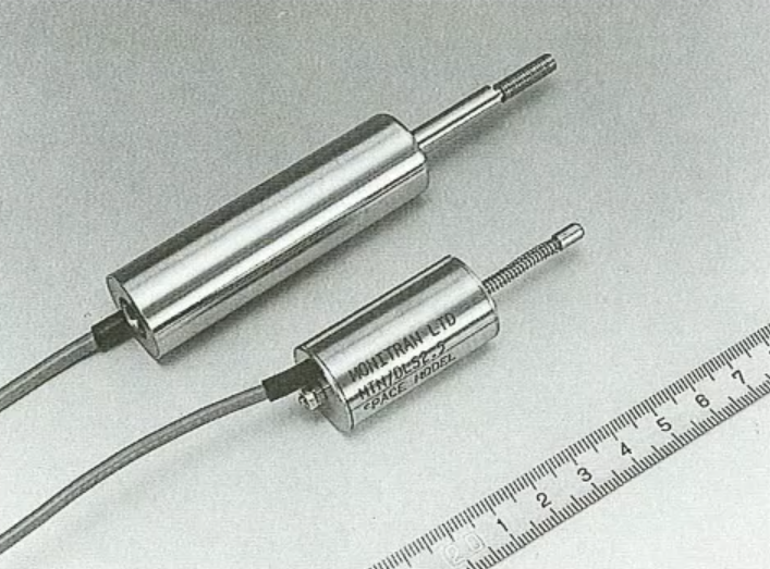
I’ll show you the structure:
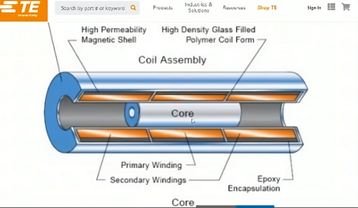
- The primary winding is the one here at center and two identical secondary windings at the opposite ends of the cylinder.
- The primary winding (or coil) here is excited by an AC voltage such that a magnetic field is created.
- The inner cylinder called the core is ferromagnetic.
- The core when the sensor is in its reference position, is perfectly centered and symmetrical with respect to the secondary windings.
⇒ The mutual inductance, between the primary and each secondary coils is exactly the same when the core is in its reference position, so the output will be . - If instead the core moves, then the structure becomes unbalanced and the mutual induction changes.
So one of the mutual induction between the primary and one of the secondary windings is increasing and the other is decreasing depending on the position of the core.
Formula used for transformers: A transformer with mutual inductance and two currents and flowing trough its two “branches”, then we will have the two voltage drops equal to (in the frequency domain):\begin{align}&V_1 = j\kern2px \omega \kern1px M \kern1px i_2\\&V_2 = j\kern2px \omega \kern1px M \kern1px i_1\end{align}
Here is the electric circuit: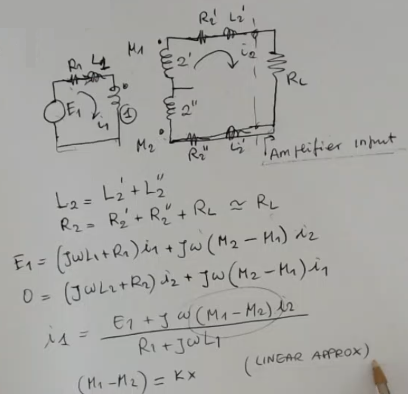
- So we have a first circuti which describes the exited core:
- : the AC exitation
- : the primary winding inductance and resistance.
- : Mutual Inductances between and and between and , which are the windings, these mutual inductances will change due to the position of the core.
The formulas governing these inductances are:\begin{align}&E_1 = (j \omega L_1 + R_1) \kern2px i_1 + j \omega (M_2 - M_1) \kern2px i_2\\&E_2= 0 = (j \omega L_2 + R_2) \kern2px i_1 + j \omega (M_2 - M_1) \kern2px i_2\\& M_2-M_1=k \kern1px x \kern15px \text{(linear approximation)}\end{align}NOTE:- The first two equations are simple voltage mesh (In italiano “maglie”), voltage equations.
- The third is a simple approximation taken arbitrarly.
Doing some calculation we get:
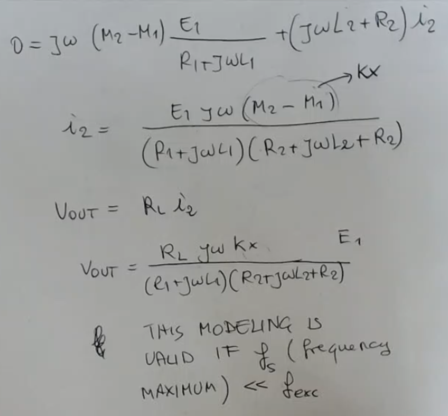
- The formula is a little wrong, there is one too much , I rewrite it:
- As we have alredy said in other cases, this is valid for .
Therefore, we can draw the transfer function of this circuit: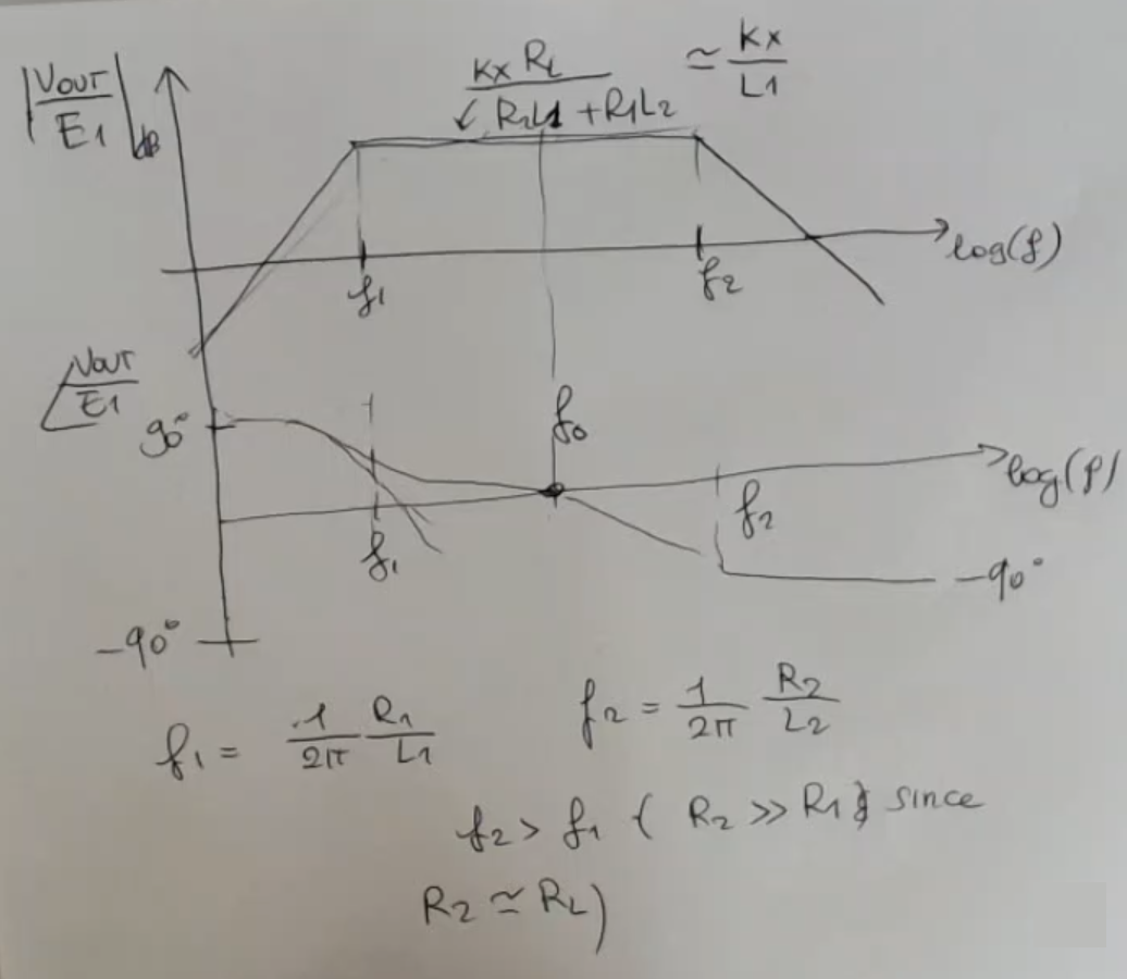
- If we suppose (as it usually is) , we can approximate:Since remember that we defined:
- As we can see from the output formula:There is a zero in zero, and two poles one at and one at .
NOTE: the phase is equal to only in one point (this is kinda exagerated but you get the point):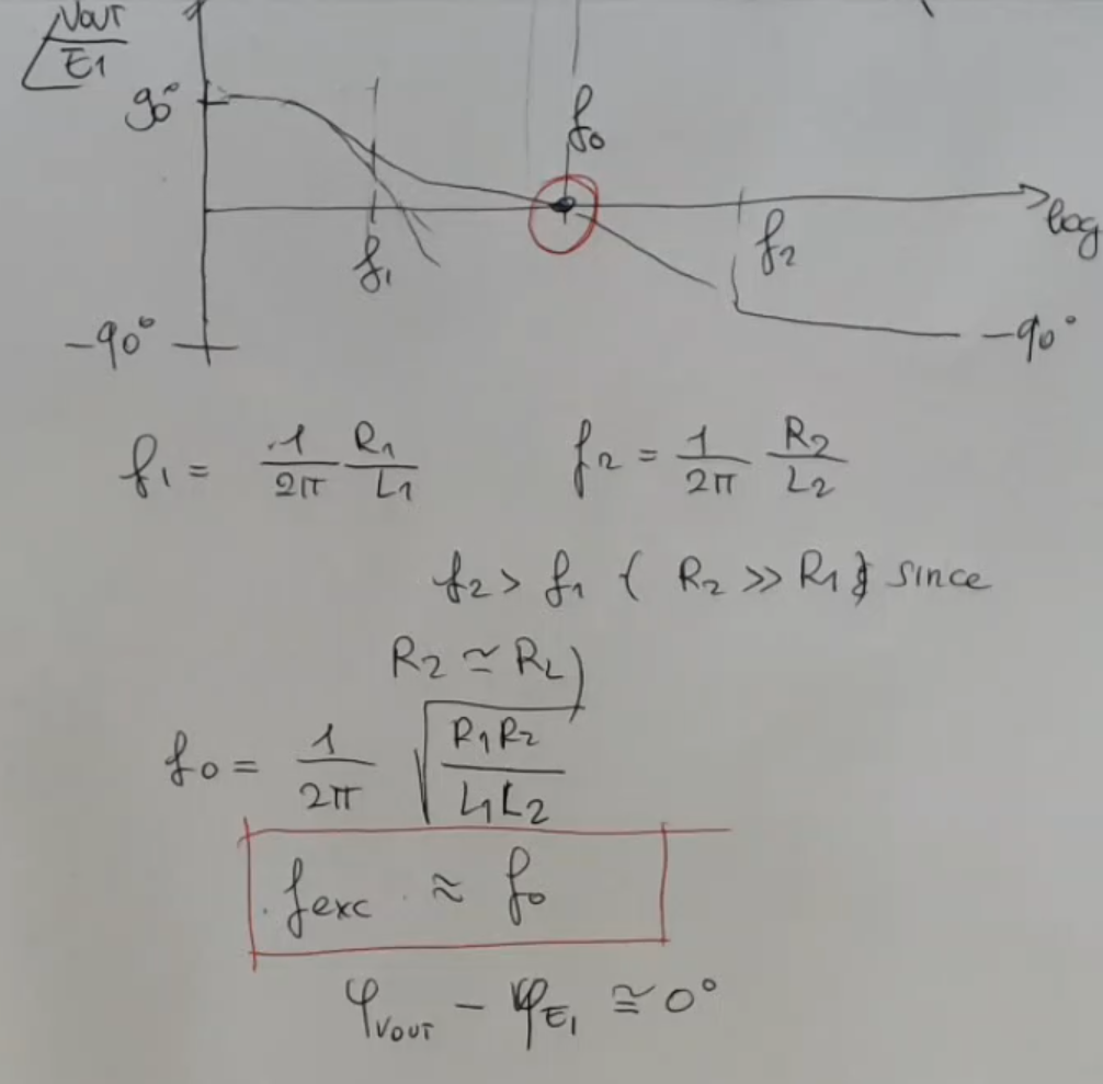
- So it will be wise to select , so that the output will be in-phase with the input.
We have considered as greater than , what happens if ?
⇒ The initial phase is shifted by and the same is true for the phase at .
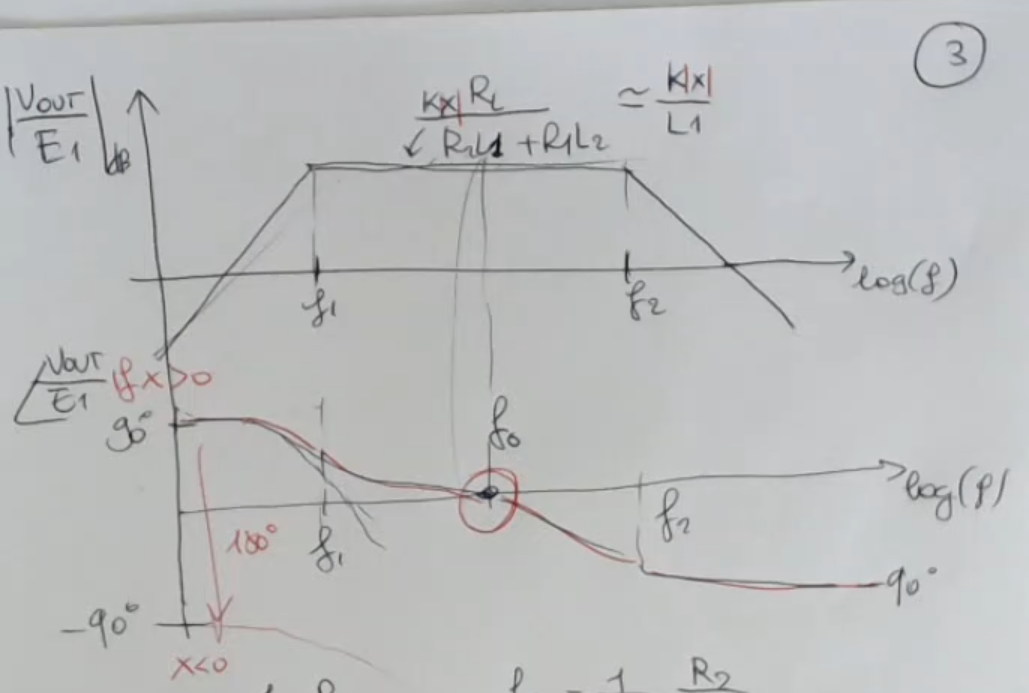
- We will lose the sign of at the output.
So if we draw the output obviously I find something like this:
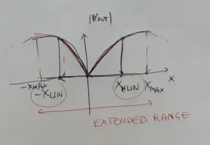
- It is simmetrical.
- We can approximate this sensor as linear if we stay in the “linear range” defined by .
- But sometimes it is accepted to work in the extended range.
- Remember that the carrier amplifier is a structure which performs an amplification but also a comparison with the phase of the input signal, in order to understand if there is a shift of 180 degrees or not.
- After this since usually the carrier amplifier gives a signal which is no more AC.
⇒ Then we need a low pass filter. - The final outptut will be the amplitude of multiplied by the sign of , also it will be a DC signal, or at most a slow varying signal.
- There exists some IC (integrated circuits) which embed all of this and are ready to be used with a sensor.