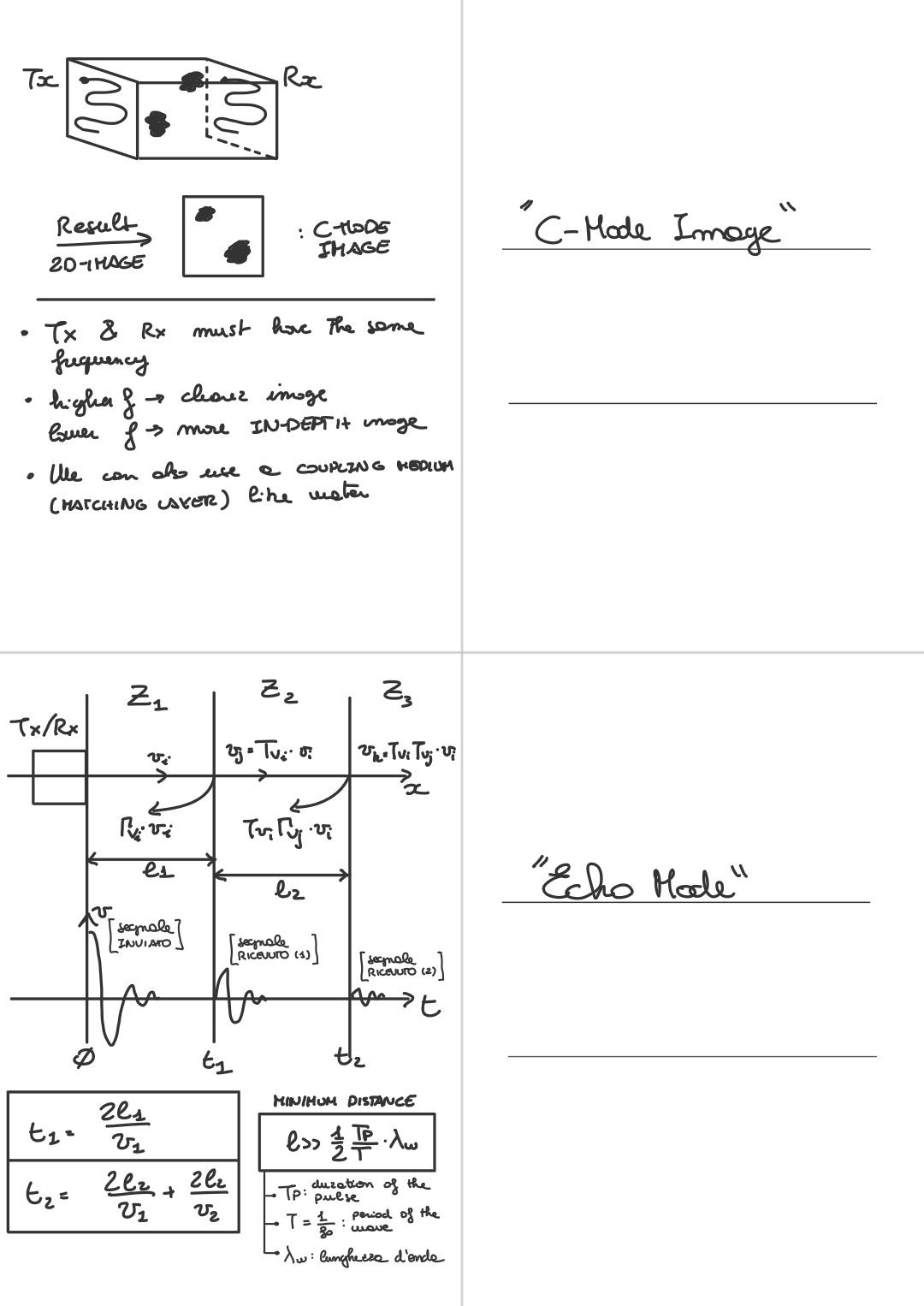
Differently from the transmission mode, in “echo mode” measurements, ==we have a single transducer== which acts as a transmitter (TX) and also as a receiver (RX). This device can't act at the same time as an actuator or as a sensor, so we need to define the phase when it acts like a transmitter, and when as a receiver.
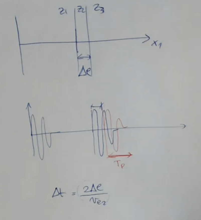
Let’s take as example a situation like this:
Where have three different mediums with the acustic impedance , then and , that means that you have different velocity and/or different density.
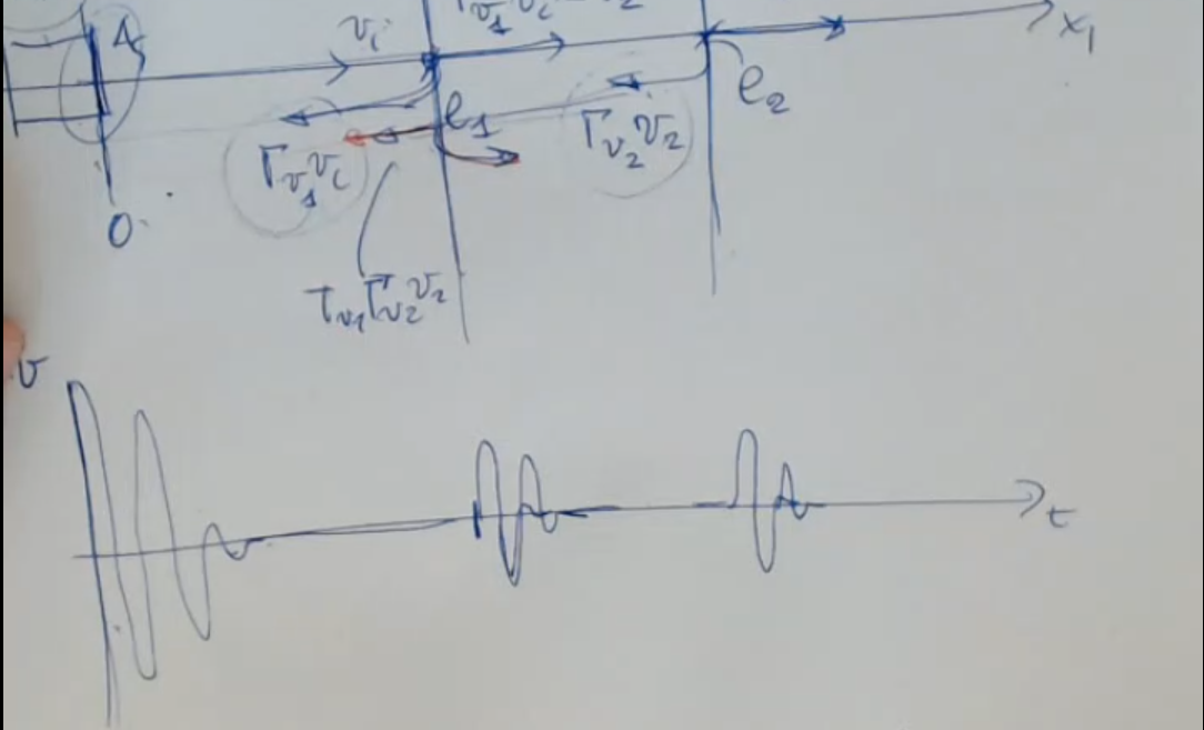
Here’s how the echo mode works: At first we have the actuation phase where it is used as an actuator/transmitter and we imagine to have a situation like this:
Sometimes if you are lucky you have the same sound speed and different density, this is very good and we'll see how.
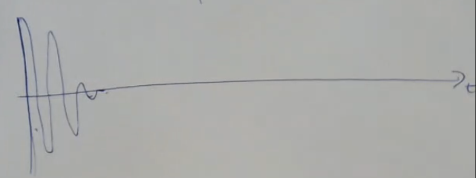
For the graph, we place which is the propagation velocity of the wave, and as for the -axis I place a timeline. The first excitation, the vibration at the beginning is strong:
So what happens the wave starts, arrives here (), some is reflected back, this echo will be then sensed by the same device that will act as a reciver (RX). ==The fraction which is reflected or transmitted depends on the mismatch between this impedances and ==.
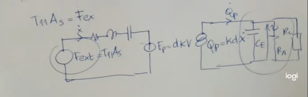
So here is the modelling of just the sensor (we ignore the TX part):
- will be very small.
- : stress along applied over the surface .
- : sensor’s surface.
So after the first excitation, a time will pass and I will recive a new signal, the echo of the first one, and ofter another bit of time () I will sense a second echo, the one “returning” from the second material.
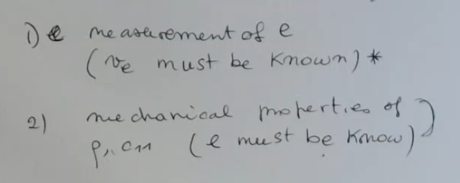
The amplitude of the first echo depends on the difference and values of and , the distance it needed to travel (due to attenuation), and the geometry or shape of the beam, simialr for the secon echo, but since it need to travel two materials, and is furter away, the amplitude and signal recived will be straight up worse. We can calculate , also called time of flight (TOF), and using these formulas:So the distances and can be evaluated if and are known.
There is also another problem to tackle, what if the three surfaces are close:
- The recived signal is the superpose of the two.
- pulse duration (duration of each echo), we must impose that .
- : “time-of-flight-difference” between the second and third material.
You can also see it as: how far away the two echos are from each other.- So we have to assure that the pulse duration much smaller than the time-of-flight-difference between the second and third material ():So, if we perform some calculations we ombtain that the must be:Where:
- from , meaning:
“The duration of the pulse is a multiple of the wave period ”- : wavelength.
- Remeber that the pulse duration must be a multiple of the period, and it cannot be shorter than one period (I send a wave , it will return scaled of intensity but still similar in shape as the wave ), so we can write:Where is the period, and is the natural frequency.
- We must have the two materials at least much more distant then
- The larger the wavelength ⇒ the larger should be , so that we get two recognizible echos
Also coincides with the -factor of the oscillator: So the higher is the -factor, the longer will be the signal duration. ==So low and short wavelength give us best performances, possible in terms of resolution==. But actually if the path is short (the signal duration), then we have a smaller energy traveling, so maybe we will have a smaller penetration depth.
We saw that in echo mode we can arrive to measure the time of flight (, , ), gieven by:Where:
- is the size of the matrial.
- the propagation velocity of the wave.
I we know , which depends on the material and , or we can find the other values:
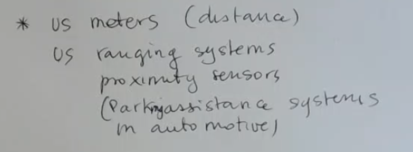
Finally US (Ultrasonic) devices can be used for:
- The last example is: “Parking assistance systems, when you are in an automotive, to understand the distance of an obstacle to be alerted by an alarm”
Memory Card