Remeber:
Here is a scheme of a MOSFET:NOT_SURE_ABOUT_THIS
Here another one:
Finally here’s a video on how a MOSFET works.
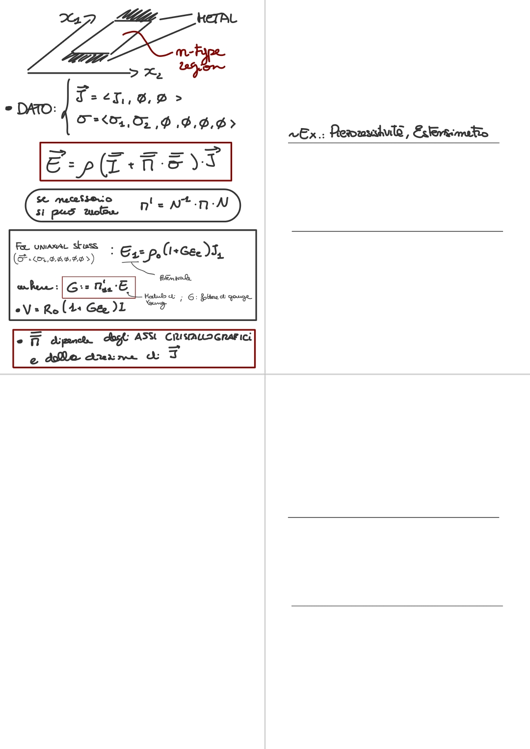
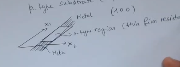
Take a thin film of -type doped silicon and place metal lines at both ends, like so:
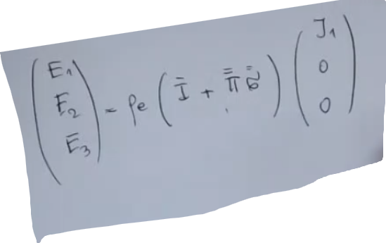
We can feed it a current from the metal ends, and we define it like so:Then we apply a stress across two direction, with respect to the current:So no shear stress, only extensive or compressive stress. If we want to calculate the piezoresisitve effect brought by this strain, and current, we can say that:Where is the piezoresistive coefficient matrix, specifically for silcon it is defined like so:
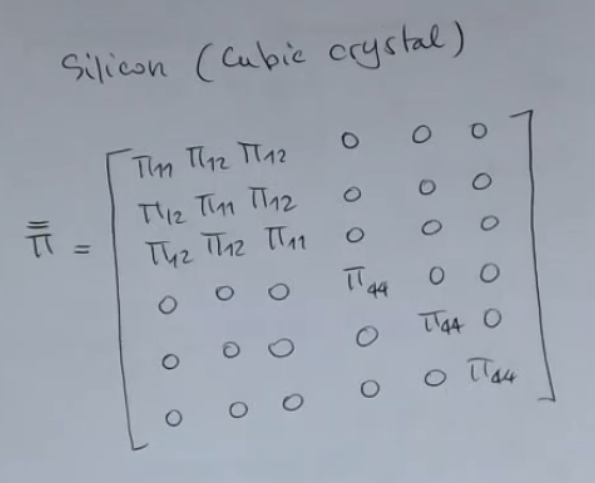
The previous formula holds true if the applied stress follows the crystallographic axis of the silicon crystal, meaning: the axis on which we apply the stress coincide with the crystallographic axis, so:However if it is not the case, we need to rotate the tensor, to do this we can simply calculate:Where: is the rotation matrix.
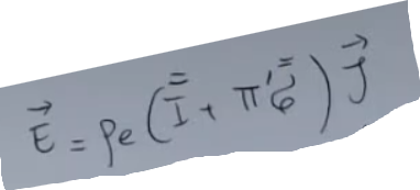
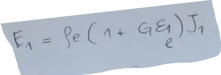
If instead we apply an uniaxial stress:The final formula would be:Where:NOTE:
- is the Young modulus.
A common value for the Young modulus in this direction , for this sensors, is GPa, so we’ll find at the end a factor which is quite large.IMPORTANTE- is the electric field.
- is the strain.
- is called the gauge factor, we have defined it when talking about strain gagues.
So if we calculate the voltage:Where: is the longitudinal strain.
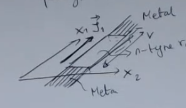
What happens if we change the direction of with respect to the voltage reading, and also if we change the crystallographic axis of the silicon crystal:
- : relative piezoresistive coefficient (transverse and longitudinal).
- ==You can see that you can either measure a voltage along the direction of the current, or the perpendicular to the direction of the current==.
Memory Card
Index
- p-Type Substrate Composition
- Piezoresistivity on Planar Stress
- Rotated Matrix
- Uniaxial Stress
- Piezoelectric Longitudinal Coefficient
p-Type Substrate Composition
Piezoresistivity on Planar Stress
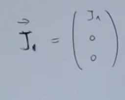
current density vector:
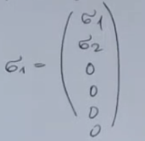
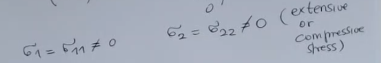
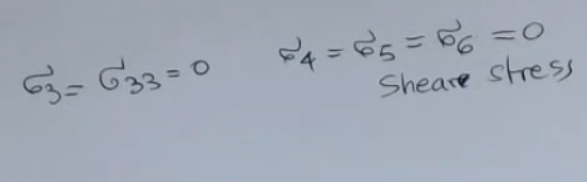
stress tensor, we apply stress only in two directions, planar stress:
So in this case, I can write the relationship we have found before:
But If , are rotated with respect to the crystallographic axis,
simply when creating the resistors I rotate it with respect to the crystallographic axes: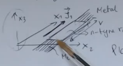
==So if and are rotated with respect to the crystallographic axis, I have to change the matrix, and I have to replace it with the matrix which is the rotated version of the “normal” resistive coefficient matrix==: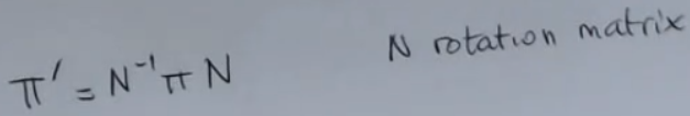
The rotated matrix does not maintain the same symmetry: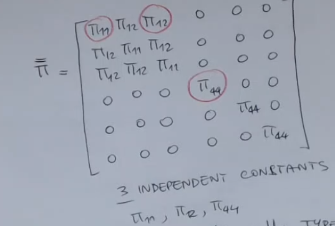
- So we may have some non-zero elements where we expected the zero.
- So it loses the shape, the symmetry seen above.
- It can be for instance a full matrix.
Rotated Matrix
So the more general formula accounting for the Rotation Matrix:
 Where:
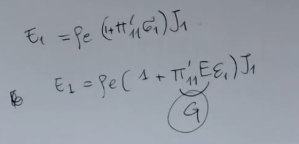
Uniaxial Stress
Obviously, if we are looking at what happens when I have a uniaxial stress: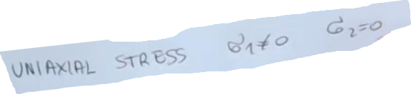
- is the gauge factor for a piezo resistive strain gauge.
So for piezoresistances we have found an expression which is similar to what we have found for strain gauge made of metal and this is what we found: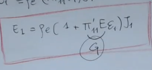
- : longitudinal
- Voltage drop
is proportional to the base resistances, because this is strictly related as we have seen to the current flow: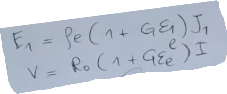
And this time the gauge factor is the product of the Young modulus () times the piezo coefficient in the right direction: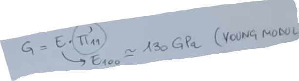
And since the Young modulus in this direction here (), for silicon, is equal to GPa, you’ll find again at the end a factor which is quite large.
Piezoelectric Longitudinal Coefficient
So here is what happens in different cases with piezoresistances which are oriented according to the vector below each image: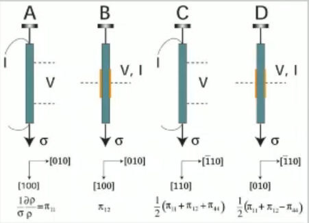 Also you can see the relative piezo coefficient (transverse and longitudinal)
==And you can see that you can either see a voltage along the direction of the current, or the perpendicular to the direction of the current==.
Also you can see the relative piezo coefficient (transverse and longitudinal)
==And you can see that you can either see a voltage along the direction of the current, or the perpendicular to the direction of the current==.