-
Source: Internet Page | Downladed PDF
-
Amplitude:
- Real zero:
- Real pole:
- Imaginary zero:
- Peak at
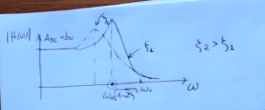
- Imaginary pole:
- Peak at
-
Phase:
- Starting Phase*:
- if ( is the gain)
- if ( is the gain)
- Real zero:
- Real pole:
- Imaginary zero:
- Imaginary pole:
- Starting Phase*:
-
Frequency Domain Response (Bode Form):
- For a single-pole system, the transfer function in frequency domain is represented as: , where is the DC gain and is the cutoff frequency.
- Cutoff frequency () or frequency is related to the time constant as: .
-
Bode Plots:
- The module of is represented in dB as .
- The DC gain () is the value of when .
- The cutoff frequency () corresponds to in dB.
Gain
- A real zero means , where is its multiplicity
- A real pole means , where is its multiplicity
- An imaginary zero
- means , where is its multiplicity
- In the case of an imaginary zero there is a also peak is at
- An imaginary pole:
- means , where is its multiplicity
- There is a also peak is at
- ~Ex.:
Phase
- Starting Phase*:
- if ( is the gain)
- if ( is the gain)
- Real zero: , where is its multiplicity
- Real pole: , where is its multiplicity
- Couple of conjugate complex zero: , where is its multiplicity
- Couple of conjugate complex pole: , where is its multiplicity