Remeber:
- Suppose you have a non-ferromagnetic target, so the target’s permeability is approximately , actually if it’s exactly the reluctance will not change at all.
⇒ So theoretically from the modeling that we have done untill now, there is no way of sensing the proximity of this non-ferromagnetic target because the overall reluctance (insiede and outside the target) is constant.- But if this non-ferromagnetic target is conductive, what happens is that the variation of the flow inside (due to the AC exitation), generates currents.
Obviously, this happens if the variation are large enough, and so this current becomes important.- These current which is an induced current, let’s call it , is called Eddy Current, and are due to the voltage which generates in the target () :
- This Eddy current, forms a magnetic field which opposes to the variation of the flux.
Therefore ==the best way to model everything is to consider the mutual induction==.
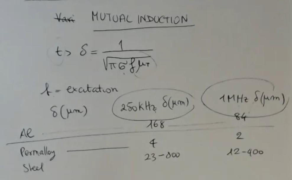
- However to have a measearable effect, I need that the thickness of the target () to be larger than the “skin depth” or “penetration depth of the magnetic field” (), so:Where:
- : the conductivity of the target.
- : frequency of the excitation.
- : permittivity of the target.
- Here’s the skin depth, measured in , per IMPORTANTE
- Alluminum:
- Permalloy:
- Steel:
- NOTE: ==In order to have this eddy current effect to be “usable”, usually we use very high frequency==.
We model the Eddy Currents like this:
- And the resulting impedance will be equal to: And since the final formula is too complex just remember that the resulting impedance: And that both and depend linearly from .
- So Eddy currents probe can be used, but they need to be calibrated depending on the material.
Which is especially important if the material is also ferromagnetic.- Let’s see how the equivalent percentance inductance , changes with respect of the distance to the target and the material:
- NOTE:IMPORTANTE
Some materials increases their inductance , like Stell.
While other decreases their inductance, like for example Alluminum.
Also the percentange change of can assume values of around .
- ==We have previously disregarded of the effect of Eddy Currents, because we have considered the reluctance the most relevant variation, and also we have considered low frequencies==, so the induced current played a minor role.
- A typical front end for this kind of objects, which has to operate at very high frequency is for instance: an FM modulated system:IMPORTANTE
(However the strucutre is NOT IMPORTANT):- The frequency which are used with this kind of probes is let’s say also in the order of .
Memory Card
Index
- Eddy Currents
- Maximum Thickness
- Lumped Parameter Circuit
- Target Characteristics
- Target Characteristics
- Eddy Probe
- Small Recap on VRS and Eddy Current
Eddy Currents
There is also another effect that we have not considered up to now.
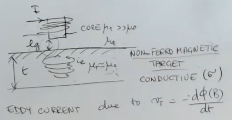
- We suppose to have a non-ferro magnetic target so , so the target’s permeability is approximately , actually if it’s exactly the reluctance will not change at all.
⇒ So theoretically from the modeling that we have done, there is no way of sensing the proximity of this non-ferromagnetic target because the overall reluctance (insiede and outside the target) is constant. - But if this non-ferromagnetic target is conductive, what happens is that the variation of the flow inside (due to the AC exitation), generates currents.
Obviously, this happens if the variation are large enough, and so this current becomes important. - These current which is an induced current, let’s call it , is called Eddy Current, and are due to the voltage which generates in the target ().
Maximum Thickness
This Eddy current, forms a magnetic field which opposes to the variation of the flux.
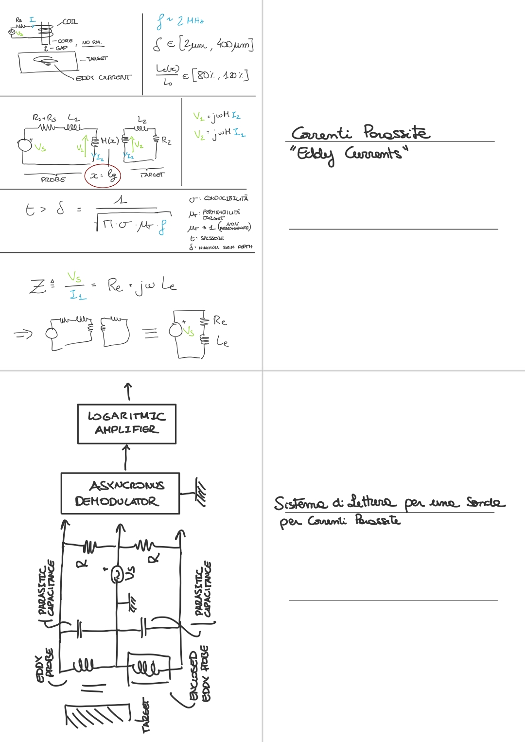
Therefore the better way to model everything is to consider the mutual induction:
- The effect that the coil has on the target is like the primary of a transformer.
Instead the Eddy current flowing is like the current induced in the secondary of a transformer. - We can model everything using mutual induction, but before going on, I will also show you that if is the thickness of the target, then I need that the thickness of the target has to be larger than the “skin depth” or “penetration depth of the magnetic field” (), so:Where:
- : the conductivity of the target.
- : frequency of the excitation.
- : permittivity of the target.
- I need this to be larger than in order to get actually a real and appreciable effect.
- To have an idea, I can put here the minimum thickness for different material, and for different frequencies:
NOTE: measured in m ( m): - ==In order to have this eddy current effect to be “usable”, usually we use very high frequency==.
Lumped Parameter Circuit
So this is the situation:
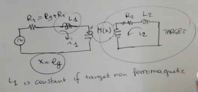
- We model the Eddy Current effect with a transformer defined by the mutual inductance .
- , , is the electrical circuit which models the input (core + coil).
- , , , is the electrical circuit which models the target.
- The mutual inductance here depends on (the gap), so the distance between the target and the probe, because the field is more intense if you are closer to the tip of the probe.
- If the target is non-ferromagnetic ⇒ is constant, or approximately.
Formula used for transformers: A transformer with mutual inductance and two currents and flowing trough its two “branches”, then we will have the two voltage drops equal to (in the frequency domain):\begin{align}&V_1 = j\kern2px \omega \kern1px M \kern1px i_2\\&V_2 = j\kern2px \omega \kern1px M \kern1px i_1\end{align}
So we can write:
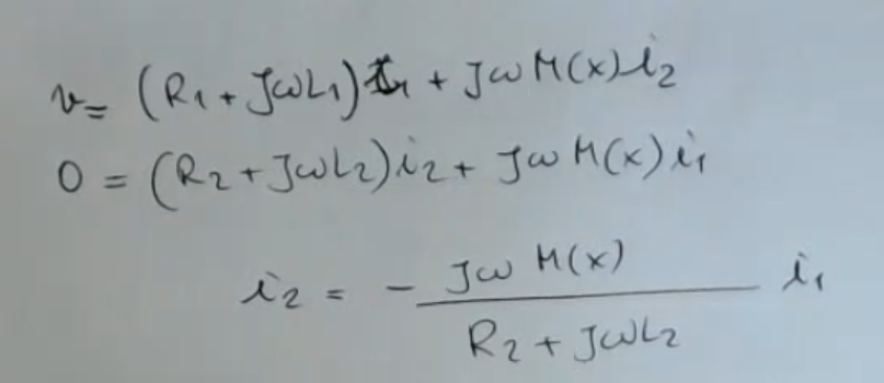 : “voltage” formed inside the target, the formula it is a bit messy I will rewrite it:
Then we can calculate:
: “voltage” formed inside the target, the formula it is a bit messy I will rewrite it:
Then we can calculate:
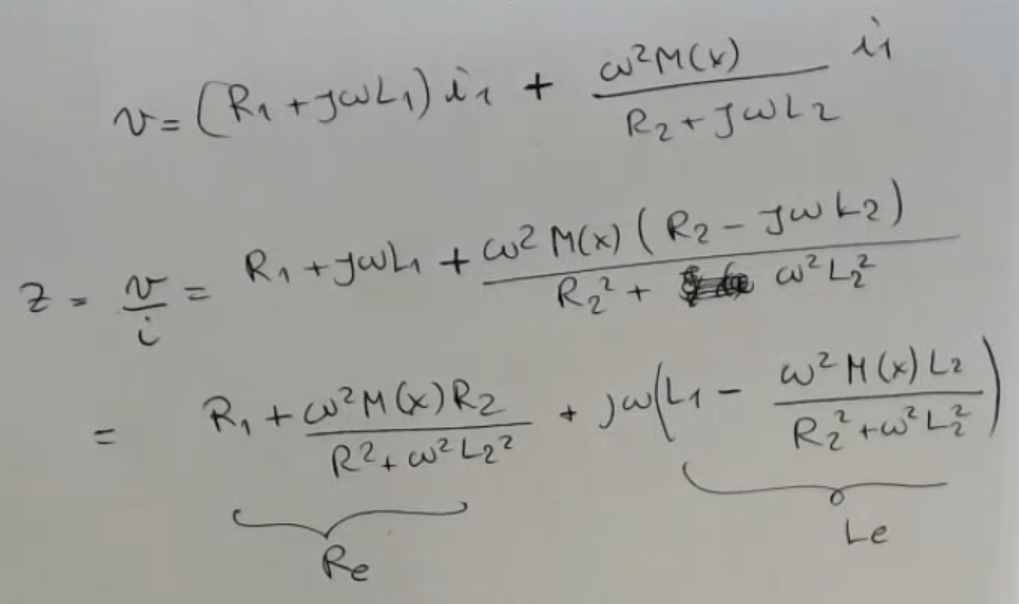
- the impedance seen by my generator defined as .
- : equivalent resistance.
- : equivalent inductance.
Target Characteristics
What happens if instead the target is also ferromagnetic (not only conductive)?
⇒ Then we will have an equivalent reluctance which varies with .
- So Eddy currents probe can be used, but they need to be calibrated depending on the material.
Which is especially important if the material is also ferromagnetic.
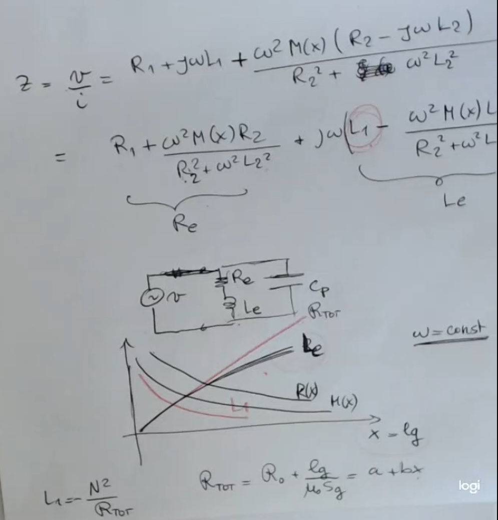
So we have an impedance and also an inductance that depend on:
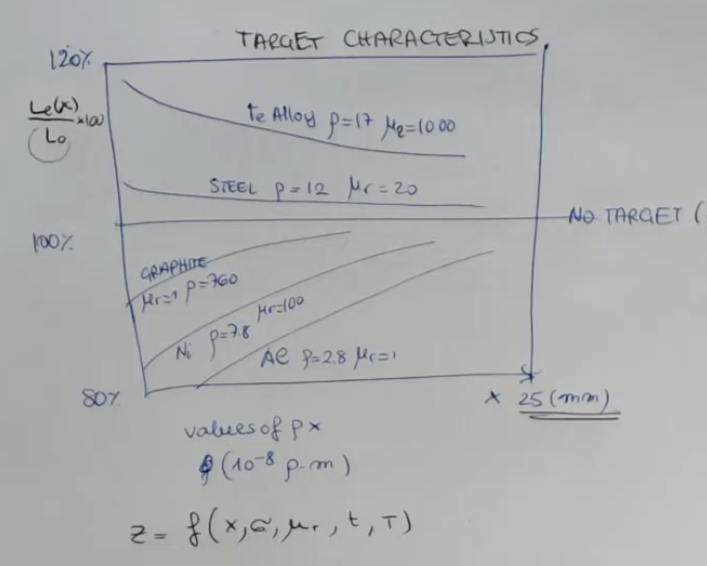
- Here you can see the ratio between the equivalent inductance (), as a function of and the reference value (which is the no-target reference, so vacuum in front of the tip).
- The scale is in percentage.
To understand we take the example of the iron alloy: when it is very close to the target will have a increased value with respect to the “no-target reference”. - So the total impedance will depend on:
- Gap distance ().
- Conductivity or instead we can say resistivity .
- Then also on the temperature , because temperature is affecting the behavior of the conductivity of the material.
- The permeability of the target .
- The thickness of the target.
Because obviously in case we have a small thickness, we will confine the currents in a smaller range, and so we have a reduced effect of the parasitic current.
(So in case we do not respect the rule)
Eddy Probe
- ==We have previously disregarded of the effect of Eddy Currents, because we have considered the reluctance the most relevant variation, and also we have considered low frequencies==, so the induced current played a minor role.
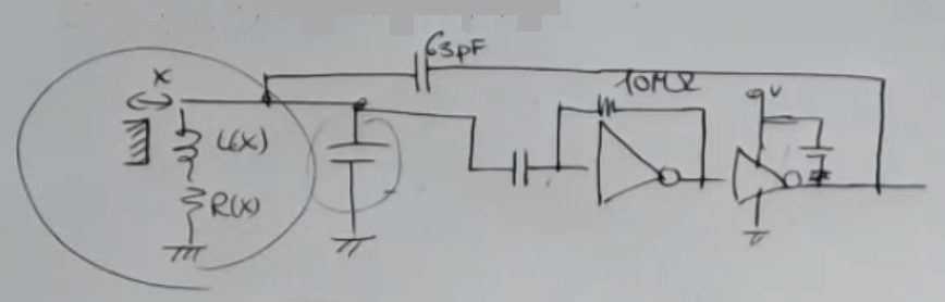
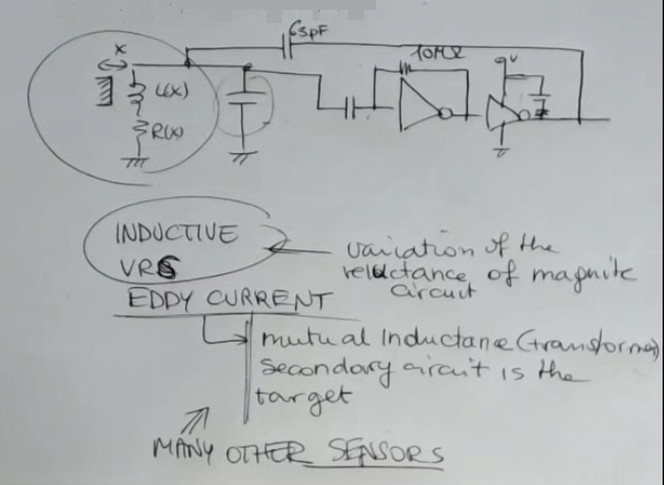
- A typical front end for this kind of objects, which has to operate at very high frequency is for instance: an FM modulated system.
- And this is a front end structure, I don’t want you to remember it, it’s here only to understand which kind of solution I usually adopted for this kind of probes.
- And in this case obviously the oscillating frequency depends on the value of this inductance and resistance , but there are also many other types of circuit, obviously.
And the frequency which are used with this kind of probes is let’s say also in the order of .
Small Recap on VRS and Eddy Current
We can recap for a moment which kind of sensor we have studied in detail.
So we have essentially divided sensors into:
- Where we had Inductive VRS (variable reluctance).
- Where we had Eddy Current.
Inductive VRS are based on variation of the reluctance of the magnetic circuit.
Instead Eddy Current ones are different, the principle of measurement relies on mutual inductance (we have modelled it as a transformer). Where the secondary circuit is the target, and it depends on the primary which is the probe, which also depends on the secondary. ⇒ So there is a mutual coupling and mutual inductance which varies due to the different position of the target and of the inducing circuit (the primary circuit).
On this kind of principle many other measurement devices, so sensors, can be found in industry.
So there are many devices which can measure speed or position, especially angle or position, based on transformer structure where primary and secondary circuits can move with respect to the other.
 So we have studied the eddy current probe but there are many other like a tachymetric circuit, and so on.