Remeber:
The transmission probe (TX) and receiver probe (RX) are two distinct devices. Here’s how the “Transmission Mode” works:
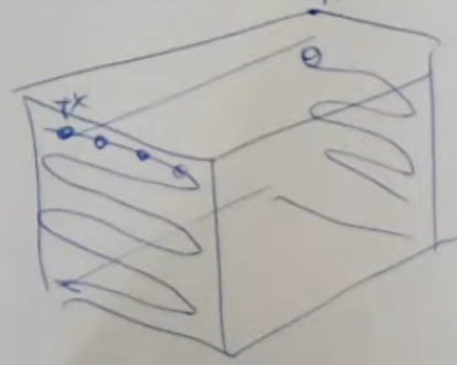
- We start with a block of material:
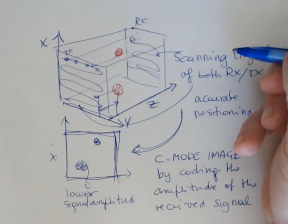
We define the path that both TX and RX will take, at two different end of the material.
We assume some imperfections are to be found inside this block, these imperfection have acustic impedance different from that of the block .- Remeber that the signal from TX to RX will travel, so it will be attuanated.
So if RX does recive a signal, we can say that the linear path from TX to RX is clear.
However if the signal is not recived, that means it has been deflected, so there is an impurity with different impedance in between.- There could be the case where the impurity is so small, that the signal is scattered, this way both the RX and TX will recive a really small signal back (rember both can work as a reciver and transmitter)
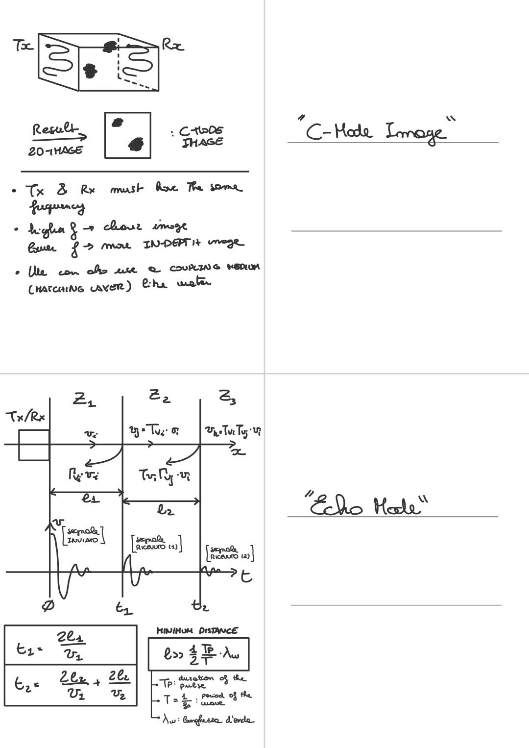
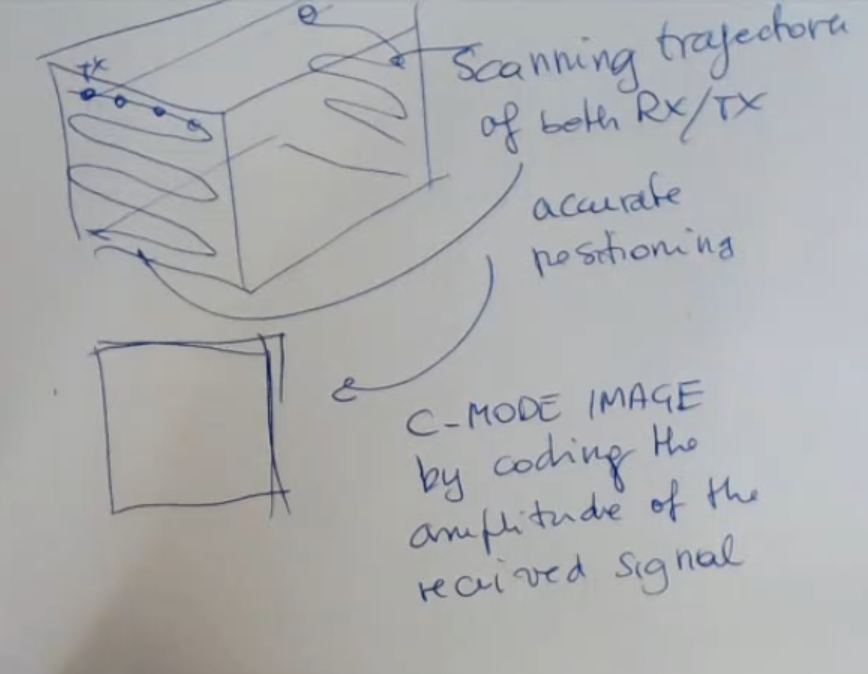
- We “scan” the whole material, so we move along the path we defined at the begininning and finally we obtain the C-Mode Image of the material:
In red we can see some difects, that are then shown in the C-Mode Image.
Here’s how we can manipulate the transmission mode to get more informations:
- You can change the position of RX and TX, the intesity of the signal, so that you can obtain a more clear image.
- You can reduce the frequency to see more in depth, or you can increase it to have a more clear image (but at surface level)
However ==you only see the projection in a 2D format, the two defects in the material and you don’t have any information about the depth, so the distance that you have from the surface of these two defects==.
Also rember that TX and RX must operate at the same frequency. You will need accurate scan trajectories, for both devices. The surfaces must be smooth otherwise you have many problems.
Sometimes what is done is to place the object in water and using water as a coupling medium, but this is not so easy to do. This kind of measurement, or scan is called NDT: Non Destructive Testing.
Memory Card
We start with a block of material:
- We assume some imperfections are to be found inside this block, these imperfection have acustic impedance different from that of the block
- We place 2 devices (boht can function as TX and RX), and we make them follow the same path.
- If the RX (reciver) recives a signal from the TX (transmitter), obviusly with less intensity since it has traveled, so it will be recived attuaned, then the path is clear and there are no difects in between the RX and TX.
- However if the signal is not recived, that means it has been deflected, so there is an impurity with different impedance in between.
- Also there could be the case where the impurity is so small, that the signal is scattered, this way both the RX and TX will recive a really small signal back (rember both can work as a reciver and transmitter)
And by scanning, so moving in this way the transmitter and receiver, we can obtain the C-Mode Image:
Here what it’s like with some difects
- You can change the position of RX and TX, the intesity of the signal, …, so that you can obtain a more clear image.
- You can reduce the frequency to see more in depth, or you can increase it to have a more clear image (but at surface level)
- But, ==you only see the projection in a 2D format, the two defects in the material and you don’t have any information about the depth, so the distance that you have from the surface of these two defects==.
- So the depth of the defect is not sensed, whereas the code in it X and Y are sensed, can be detected.
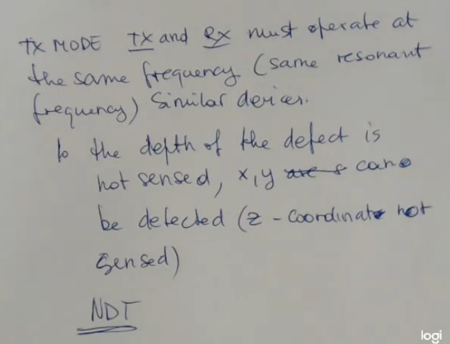
- Of course, TX and RX must operate at the same frequency,
- Also you need accurate scan trajectories, for both devices.
- The surfaces must be smooth otherwise you have many problems.
Sometimes what is done is to place the object in water and using water as a coupling medium, but this is not so easy to do. - This kind of measurement, or scan is called NDT: Non Destructive Testing.