List of things to memorize:
SaM - Capacitive Sensors
Link to original
- SaM - Types of Capacitive Sensors
- SaM - Capacitive Displacement Sensors
- SaM - Capacitive Proximity Sensors
- SaM - MEMS Capacitive Pressure Sensor
- SaM - Capacitive Accelerometer
- SaM - Capacitive Level Sensor
- SaM - Capacitive Humidity Sensor
- SaM - Capacitive (Ferroelectric) Temperature Sensor
- SaM - Readout Electronics for Capacitive Sensors (FM & AM Oscillators)
- SaM - Square Wave Oscillator
- SaM - FM (Frequency Modulation) Based on Oscillators
- SaM - AM (Amplitude Modulation) Based on Oscillators
- SaM - Complete AM (Amplitude Modulation) Circuit
- SaM - AM Modulation with 2 Sensors • Carrier Amplifier
- SaM - Switched Capacitors
- SaM - Sigma-Delta Converter (AD Converter)
- SaM - High Frequency (AC) Signals
- SaM ~ Examples of Capacitive Sensors
SaM - Types of Capacitive Sensors
- Capacitive sensor:
- displacement or proximity sensors.
- level sensors.
- temperature sensors.
- Capacitive primary sensors:
- Advantages ofcapacitive sensors:
- They are non-contact.
- Good resolution for small ranges, in the order .
- Very simple structure, the sensor is just a metallic plate, it doesn’t matter which kind of metal, usually, and it doesn’t matter the shape, two metallic plate are enough to build a capacitance.
- Disadvantages of capacitive sensors:
- Small capacitance value.
- They can work only for small ranges (small distances), this is one of the reasons because they are called proximity sensors.
We can write this simple relationship in order understand:
==The ratio: range (maximum distance that can be measured), diameter of the probe (thinking about a circular probe, a circular plate), is roughly==: - Capacitive proximity sensors are sensitive to: dirt, humidity, and to extreme temperature and extreme preassure (found in industrial applications).
- Parassitic resistance at low frequency and parasisitic capacitances at high frequencies:
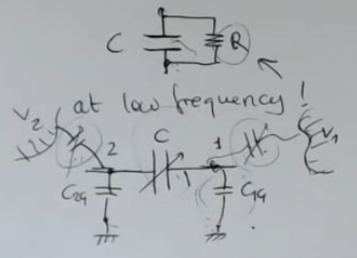
- Example with parasisitic resisitances :
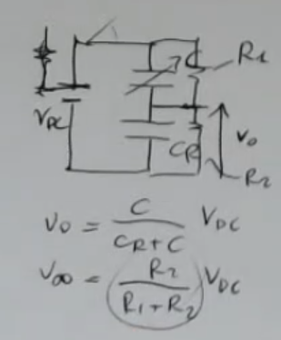
- Output at regime:(Depends ONLY on the parasistic reisistances, really bad).
- Output at the start:(Depends ONLY on the sensor and reference capacitance, good).
- Real World Measures:
- Capacitice sensor measure a value of: .
We measure with a frequency of .
⇒ The resulting impedance is equal to , which is realy large.
⇒ This high impedance will be a problem: if the front end electronic it’s not well designed, it will load the source.
Moreover, with high impedance sources, you will have electrical noise. - Capacitive sensor are small .
- They are used really close to the target (talking about proximity sensors) .
- Capacitice sensor measure a value of: .
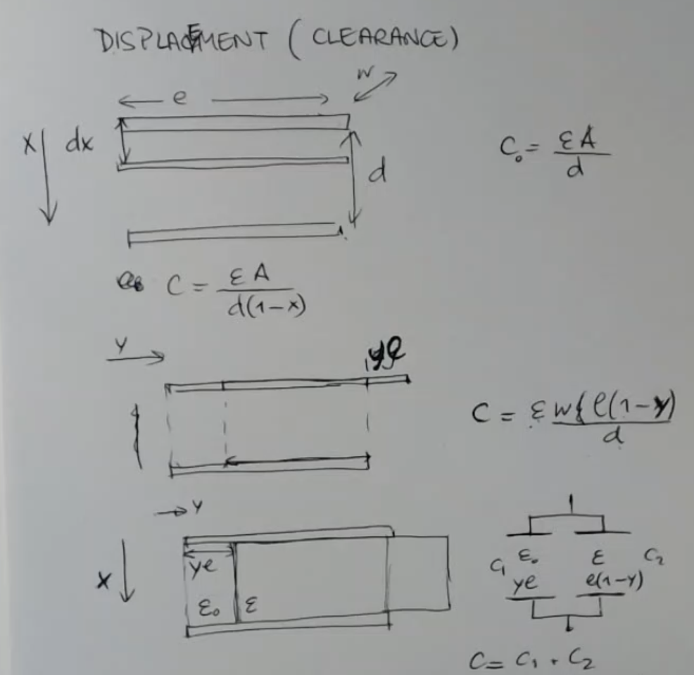
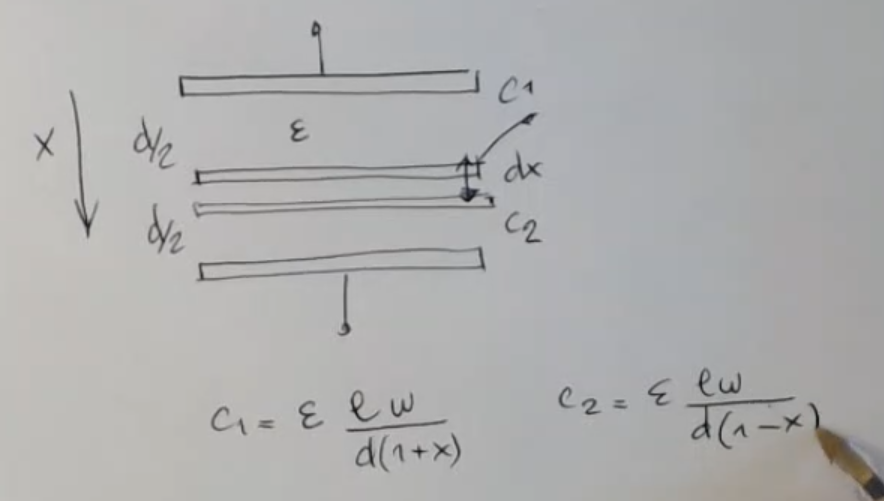
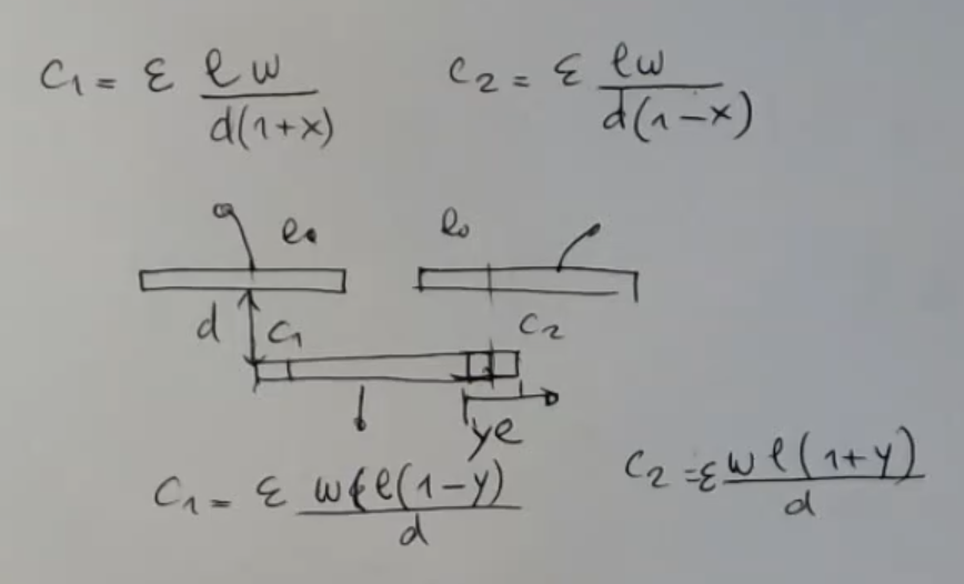
SaM - Capacitive Displacement Sensors
- Simplest capacitive displacement sensors:
SaM - Capacitive Proximity Sensors
- Structure:
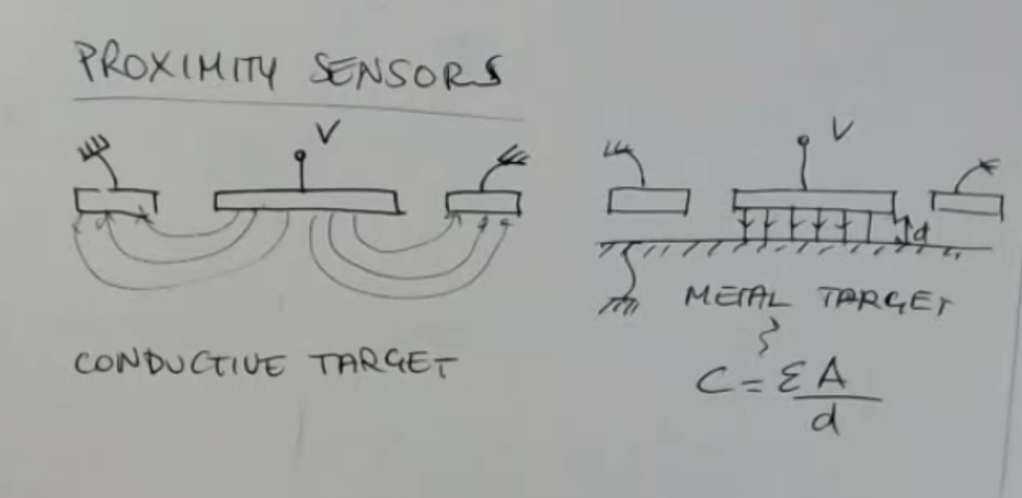
- Basic formula:
- Graph:
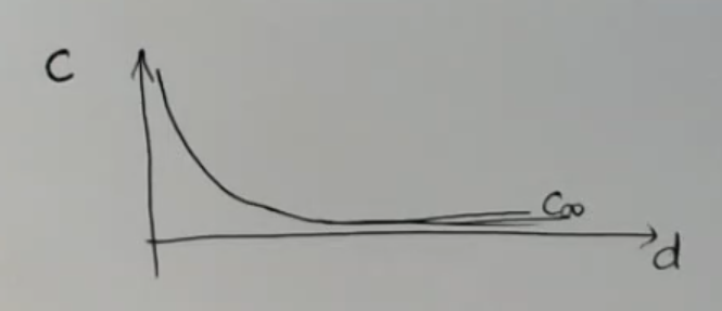
- With a large, conductive target, which is also not grounded:
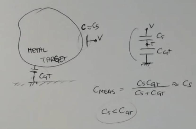
- Measured capacitance formula:If the sensor is small (if its area is small) relative to the large target ⇒ and .
⇒ ==So it’s like having a grounded conductive target (good)==. - Proximity sensor with non-conductive target:
(Can be done if the electric permittivity of the target is different from the one of the vacuum)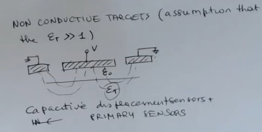
- Real World Measures:
- A circular capacitive proximity sensor with radius , measuring an object away will assume a capacitance of about .
- Impedance of a capacitive sensor:==Small capacitance means high impedance==.
- This can be mitigated by operating this sensor at high frequency.
HOWEVER: we know that the higher the frequency the most critical is the design of the electronics - We have to cope between these two requirements: keep this impedance small enough to be measured and to operate at a not too high frequencies.
- This can be mitigated by operating this sensor at high frequency.
SaM - MEMS Capacitive Pressure Sensor
- Structure:
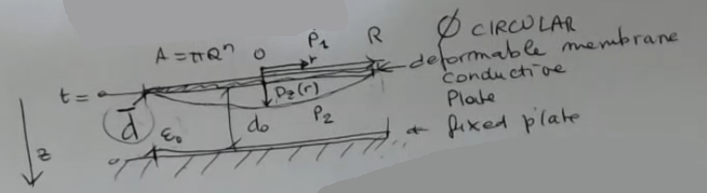
- Both the membrane and the fixed plate are conductive and act as the plates of the sensor.
- Formula:Where: is a linear function of the differential preassure:
SaM - Capacitive Accelerometer
- Structure:
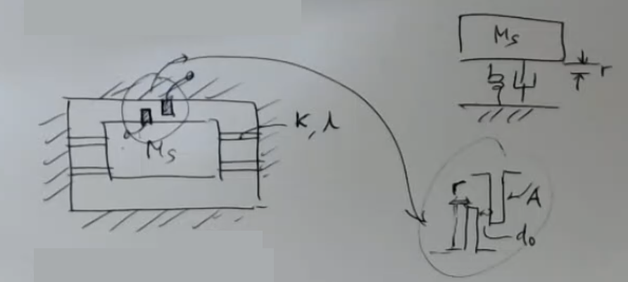
- Formula:
- Terminology:
- : capacitance value at rest.
- : constant accerelation.
- : constant sensitivity
- : sismic mass.
- : elastic constant.
- : distance between the plate, at rest.
SaM - Capacitive Level Sensor
- Structure:
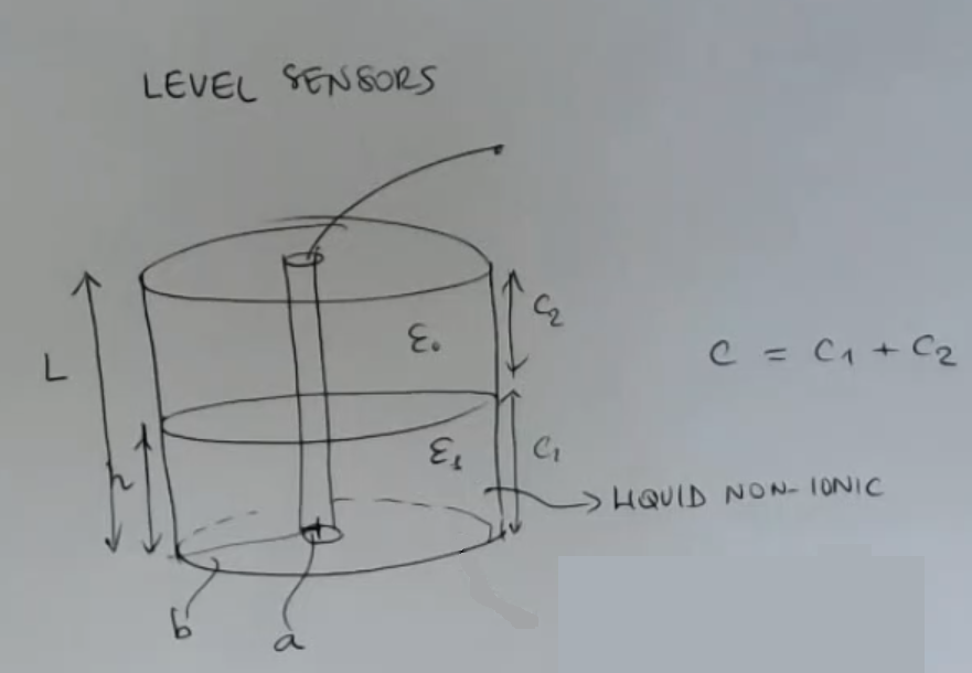
- Formula for non-ionic liquid:
- Formual for ionic liquids:Where:
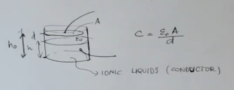
- Non-ionic liquids act like an insulator, like hetanol and water.
SaM - Capacitive Humidity Sensor
- Structure:
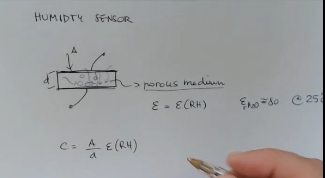
- Formula:
- Real World Measures:
- Variation of capacitance due to the humidity percentage:
- Typical capacitance value:(_This is a measurable capacitance, it is big enough, good)
SaM - Capacitive (Ferroelectric) Temperature Sensor
- Structure:
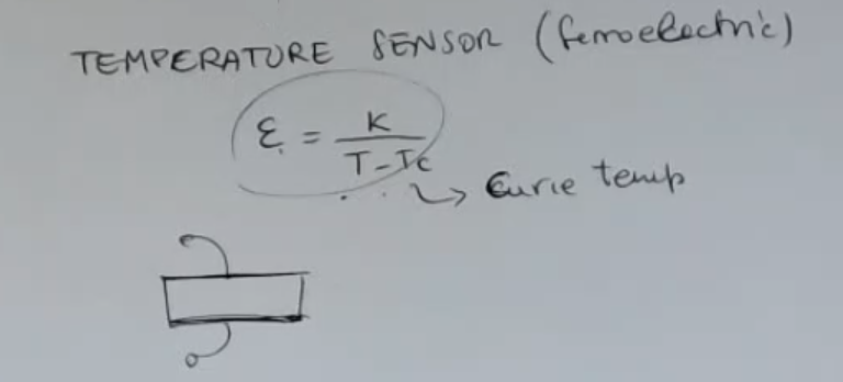
- Ferroelectric material’s electric permittivity:
- Real World Masures:
- These temperature primary sensors are really rare, since there are many other types of sensors, among which RTD sensors are very effective.
- Terminology:
- : constant depending on the material, we have not seen it in details.
- : temperature (as always in )
- : Curie temperature.
SaM - Readout Electronics for Capacitive Sensors (FM & AM Oscillators)
- We need to distinguish between:
- Low frequency signals or DC signals.
Read-out for low frequency signals:- FM: Frequency Modulation which uses a grounded sensor.
- AM: Amplitude Modulation which uses an unreferenced sensor.
- High frequency signals.
Read-out for high frequency signals:
- Low frequency signals or DC signals.
- For low frequency signals, we will need an AC exitation.
The frequency of the excitation () has to be much larger than the maximum signal frequency (), it should not be a problem since it’s a low frequecny signal.
Since the signal varies slowly, the capacitance takes a value which is constant for a long time.
This time is enough to allow the loss of the charge which is stored in the capacitors due to the parasitic resistances.
SaM - Square Wave Oscillator
- Structure:
- Formula:
SaM - FM (Frequency Modulation) Based on Oscillators
- Using a square wave oscillator:
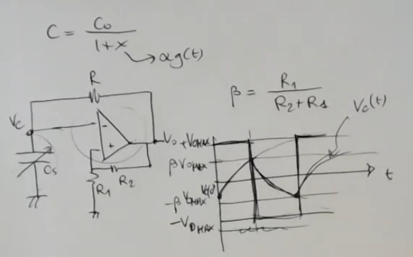
- Formula:
- Frequency of an FM modulated signal:
- FM modulation using an integrator:
(For instance if I have which is a slowly growing invariant signal, then the frequency would increase a litte over time.)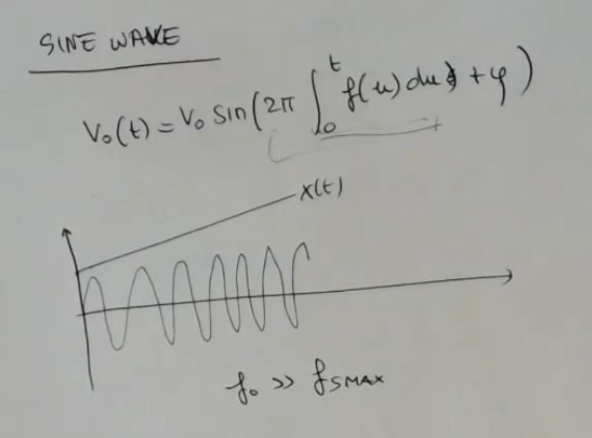
- Bandwidth of the FM modulated signal:
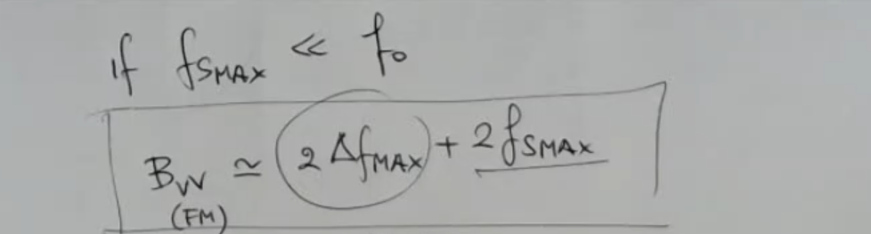
Where:- .
- And comes from: .
- Since FM transforms a the physical input variation into a variation of frequency, it is a very robust solution to reject noise.
- Complete FM Circuit:
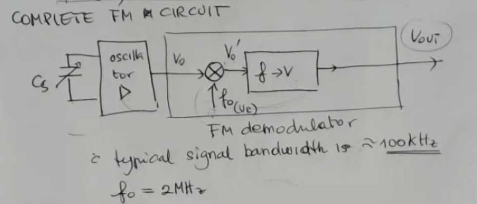
- The sensor is part of the oscillator.
- The FM Demodulator gives as output a voltage related to the frequency in input.
- Real World Measures:
- FM is used for signals which can be static but also they have a large bandwidth up to
- The typical value for is (much larger than the maximum signal frequency).
SaM - AM (Amplitude Modulation) Based on Oscillators
- Simplest circuit for AM (Amplitude Modulation):
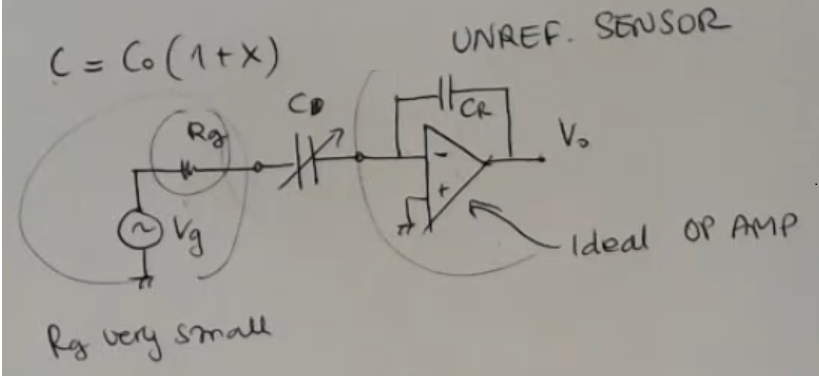
- Output:Where:
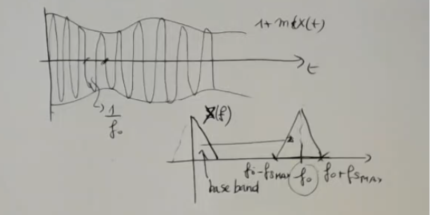
- General formula of the AM modulation:Where:
- Spectrum analysis:
- Good circuits for AM modulation:
- Current or charge amplifiers.
- AC bridges.
- Voltage dividers.
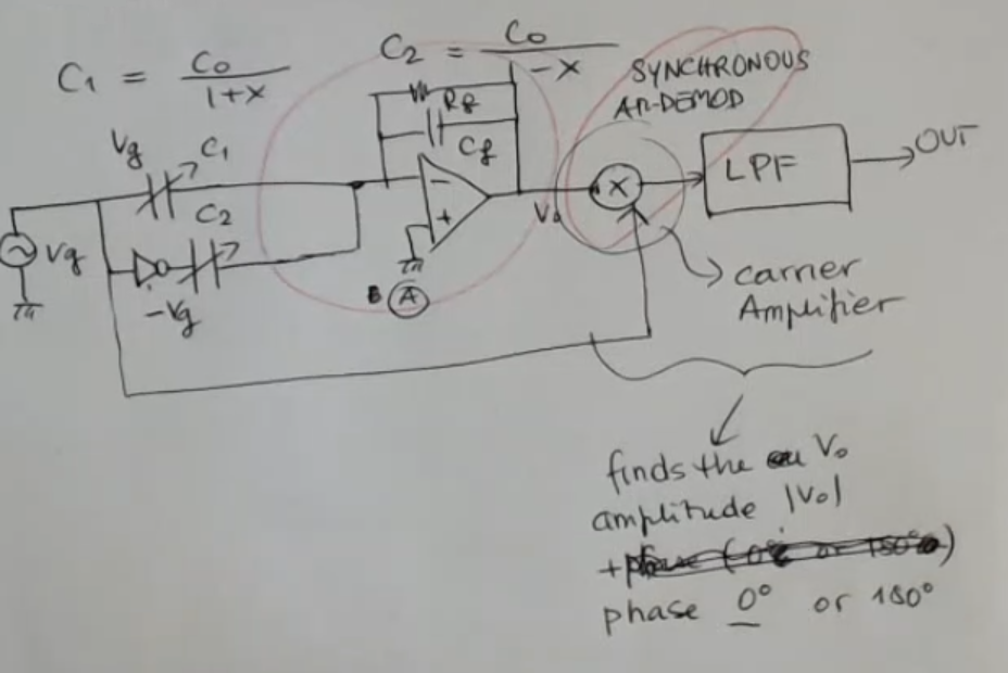
SaM - AM Modulation with 2 Sensors • Carrier Amplifier
- Circuit:
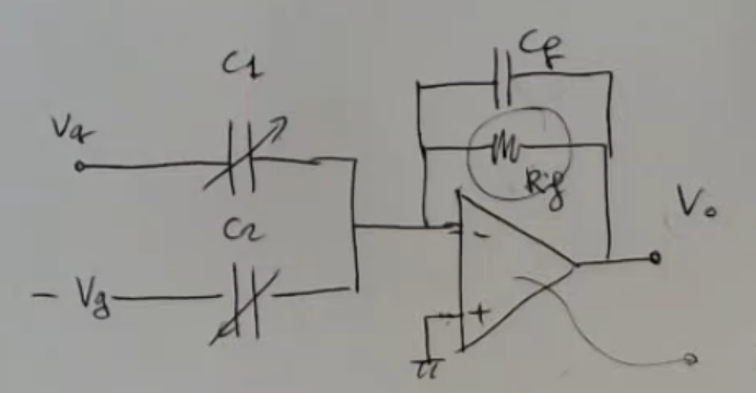
- Sensors:
- Output:
- Final formula:
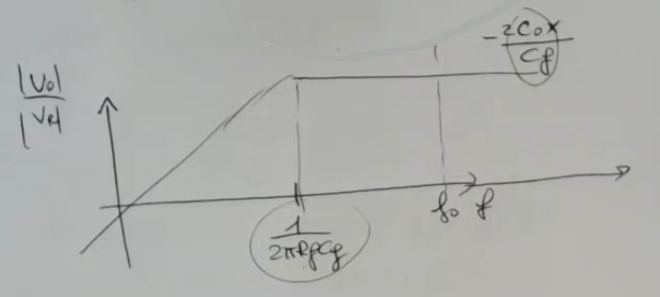
- For :(If I select a value for too large with respect to than I’ll have a very small signal, not good).
(Since this is an FM modulation, we will lose sign of ). - Bode graph:
- Complete circuit with sign-recovery:
- Real World Measures:
- , also
SaM - Complete AM (Amplitude Modulation) Circuit
- Circuit:
- This is a differential circuit, since:
- Pre-filtered formula:
- Bode graph:
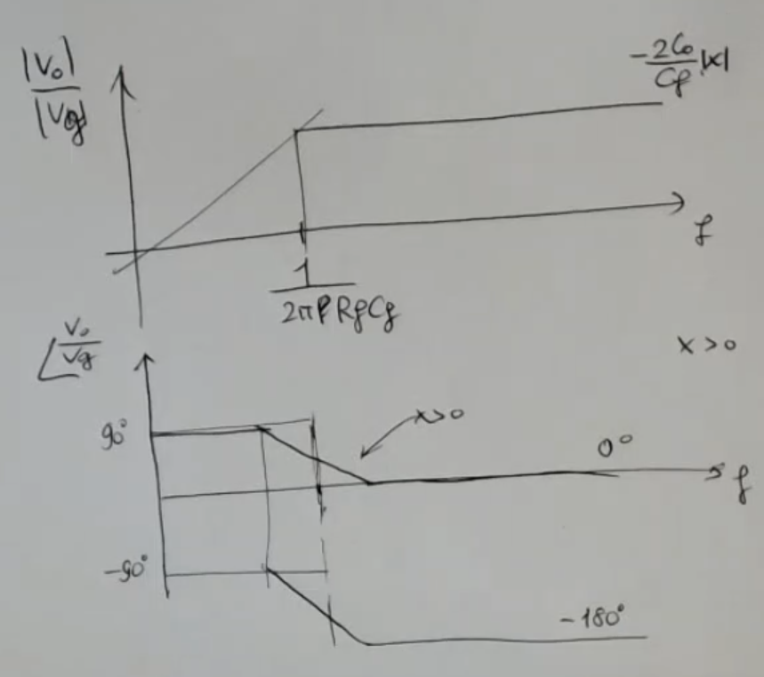
- is the lower frequency limit, defined by the feedback impedance, our frequency must be higher than this.
SaM - Carrier Amplifier
Link to original
/../../Notes--and--Images/Pasted-image-20230719105500.png)
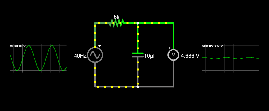
SaM - Low Pass Filter
- Circuit:
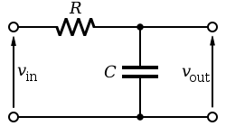
- Circuit:
SaM - Switched Capacitors
- Circuit:
(It can be used to increase the capacitance value, with respect to the sensor’s capacitance, without changing the actual capacitance)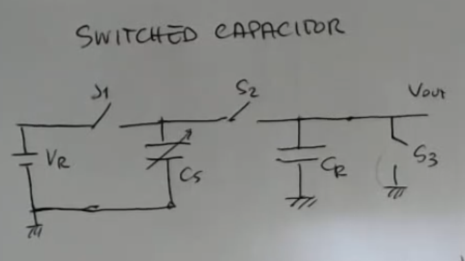
- Workings:
- START : : closed, so that we start from .
- CHARGES: (: ON, : OFF, : OFF).
- SHARE ITS CHARGE WITH : (: OFF, : ON, : OFF).
- repeat (2.) and (3.), times.
- Output at each step, relative to previous step:
- Absolute output formula:Where:
- Graph:
(If I limit the measurement ratio to , opprotunaly choosen, I will remain in the linear range)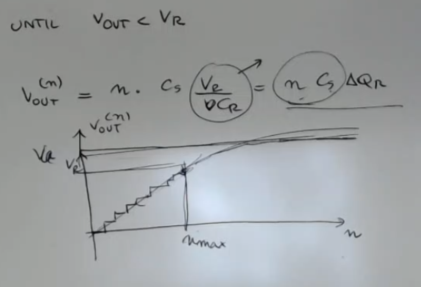
SaM - Sigma-Delta Converter (AD Converter)
- Structure:
- For this converter you need a not-referenced capacitive sensor.
- Simplified formula (based on the coffee shop example):
- Coffee shop example:
Link to original
/../../Notes--and--Images/Pasted-image-20230719105708-1.png)
/../../Notes--and--Images/Pasted-image-20230920174232.png)
/../../Notes--and--Images/Pasted-image-20230920174424.png)
/../../Notes--and--Images/Pasted-image-20230920174622.png)
/../../Notes--and--Images/Pasted-image-20230920174930.png)
SaM - High Frequency (AC) Signals
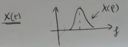
- Pure AC input signal:
- DC exitation circuit:
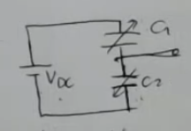
- Sensors:
- Output:
- ~Ex.: capacitive microphone electrical model:
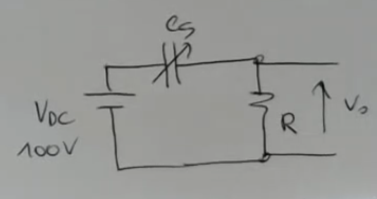
- Needed force to move the microphone’s plate:The needed DC exitation to get a readable signal would be really high, usually, it’s a large value ().
SaM ~ Examples of Capacitive Sensors
(Skipped)