Remeber:
- A Metal Strain Gauge is a passive sensor that relates its own resistence value to the deformation or strain it’s under.
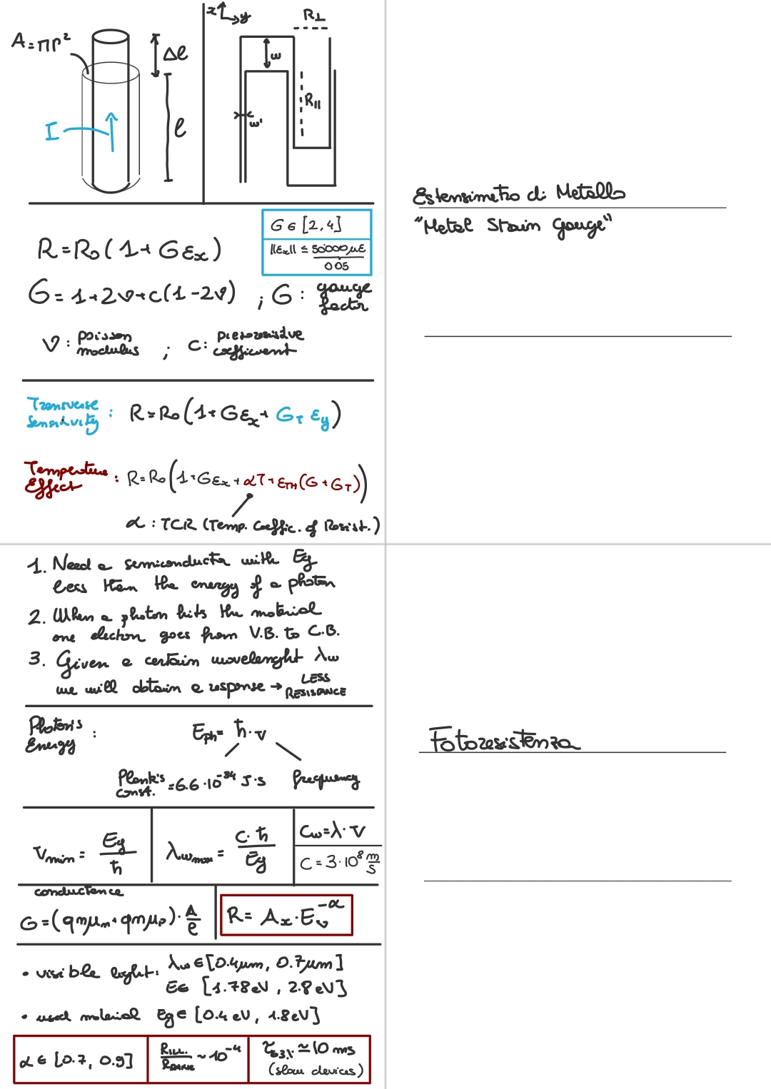
- Here we can see a scheme for a simple piece of uniform, omogeneus, isotropic bar of metal being used as a metal strain gauge:

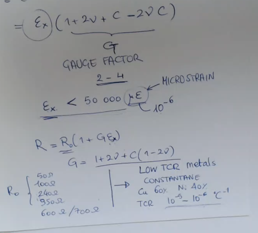
- To calculate the change in resistance due to strain, we can use the following formulas:
- And from them we obtain the percentage variation of resisitance of a strain gauge:Where:
- This formula of strain gauge is really similar to Calendar Van Dusen Equation for RTDs.
- It is important to note however that for strain gauge is at most in the order of , (or variation) so the variation of resistance is really small.
Instead for the PT100 sensor (a particular RTD sensor) the variation of resistance can even be (or variation) of its initial value.- is the strain along the -axis (can also be called ).
Its max value for normal metal strain gauges, or working range does not exceed (: microstrain, ).- is the Gauge Factor, it has values between , and it is equal to:Where:
- is the Possoin module.
- is the piezoresistive coefficient.
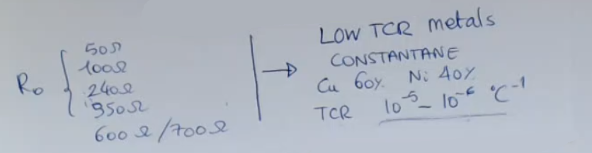
- This are some real world, standard values for metal strain gauges:
- for the strain gauge can assume the values reported above, so between .
- It is important to choose a material that has low TCR (Temperature Coefficient of Resistance), while we have seen for RTDs that the opposite is true.
The metals and alloy we choose for strain gauge have a TCR between .
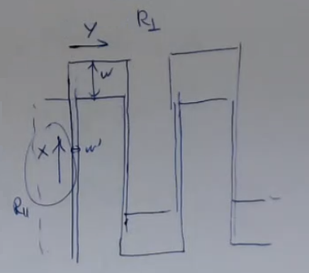
A strain gauge has this structure:
- In this way we can increase the “parallel resistance” , while keeping the “perpendicular resistance” to a low value.
==This kind of structure allows to have a small transverse sensitivity, which means we only sense displacement in the direction, and almost in the direction==.
==The sensitivity on the axis is with respect ot the sensitivity on the axis==.- However due to the “Transverse Sensitivity” created by the perpendicular resistance () we need to change the totatl resistance value, to account for this small change:Where: is the transverse gauge factor.
- For uniaxial stresses we can rewrite this formula as:Where:
- is the Poisson modulus.
- So the transverse stress can be seen as just a reduction of the gauge factor.
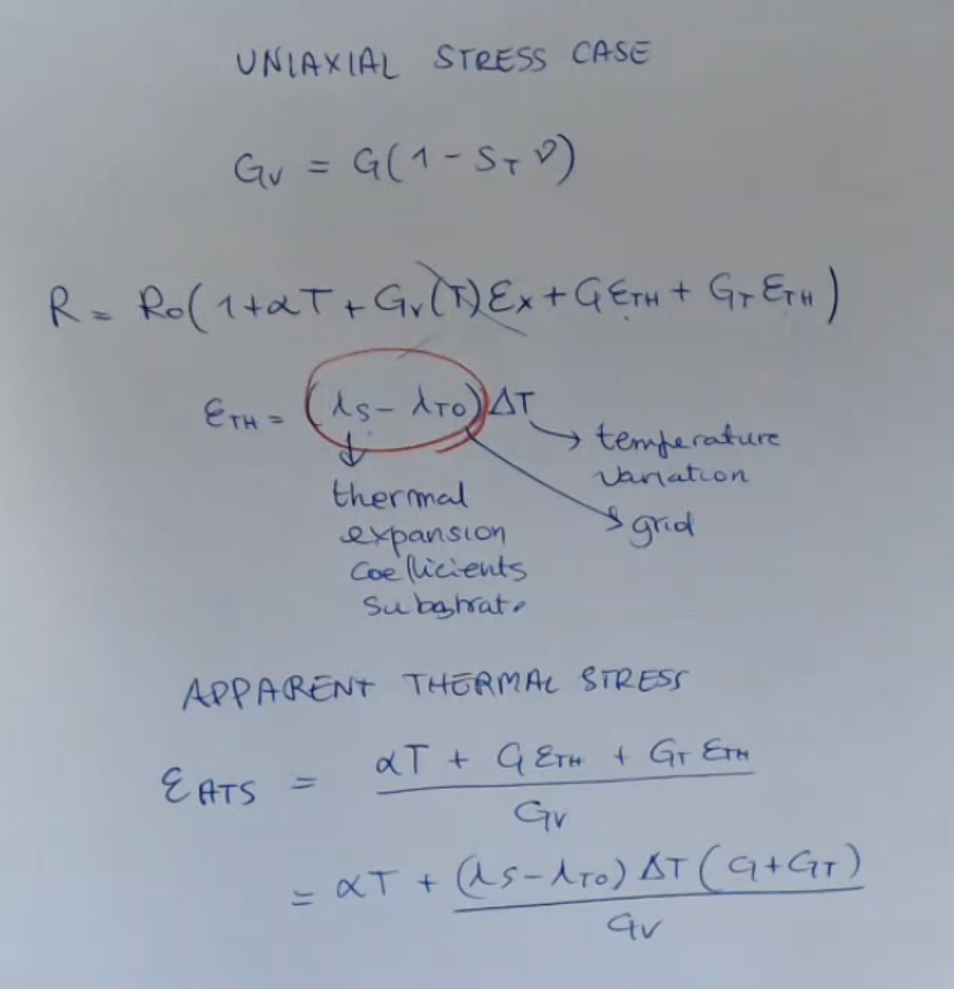
Another change that could happen, resulting in an addition or subctraction to the total resistance value is the Temperature Effect, so due to the change in resisitivity of the metal, and the thermal expansion of both the “metal grid or structure” and the substrate (the thermal exapansion will create a strain), so we need to account for:
- The TCR was first seen in the RTD lecture.
- The TCS will be ignored since too small.
- For the Thermal exampansion we need to define two coeffieicents:
- : thermal exampsion coefficients of the substrate.
- : thermal exampsion coefficients of the metal grid or structure.
So we have that, if we account for all possible changes to the resistance we obtain:Where:
Here some other material:
Memory Card
Index
- Definition of the Gauge Factor
- ~Real World Example • Standard Values for Metallic Strain Gauges
- How is a Strian Gauge Made
- How Transverse Sensitivity Affects a Strain Gauge
- Temperature Effects
- ~Ex. Temperature Effects • Uniaxial Stress Case
- Relative Variation of Resistance for Metals and Semiconductors
Definition of the Gauge Factor

- As we have seen the piezoresistivity effect for metal is:
So if we calculate the percentage variation of resisitivity of a metal strain gauge we obtain:

~Real World Example • Standard Values for Metallic Strain Gauges
Also for strain gauges we always have that is:
- is “microstrain” and is a conventional measurement unit that is equal to , since the strain is a pure number.
- The formula of strain gauge is really similar to Calendar Van Dusen Equation for RTDs.
- It is important to note however that for strain gauge is at most in the order of , (or variation) so the variation of resistance is really small.
Instead for the PT100 sensor (a particular RTD sensor) the variation of resistance can even be (or variation) of its initial value.IMPORTANTE - for the strain gauge can assume the values reported above, so between .
- It is important to choose a material that has low TCR (Temperature Coefficient of Resistance), while we have seen for RTDs that the opposite is true.
The metals and alloy we choose for strain gauge have a TCR between .
How is a Strian Gauge Made
The metal used to make a strain gauge is placed in a particular pattern:
In this way we can increase the “parallel resistance” , while keeping the “perpendicular resistance” to a low value.
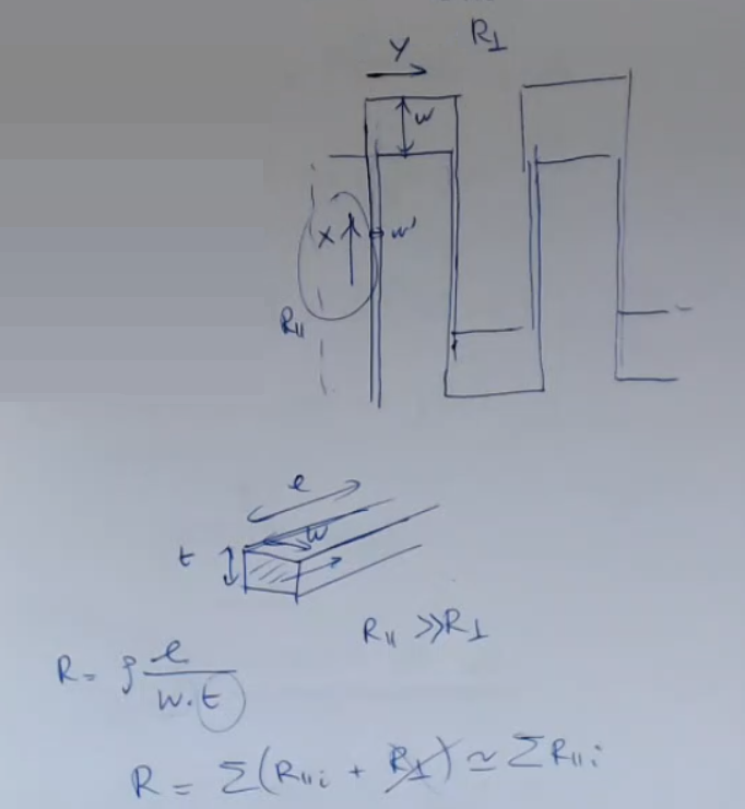
- is defined as the sum of all the thin and long parts of the total resistance.
- is defined as the sum of all the thick and short parts of the total resistance.
- so can be ignored.
==This kind of structure allows to have a small transverse sensitivity, which means we only sense displacement in the direction, and almost in the direction.
The sensitivity on the axis is with respect ot the sensitivity on the axis==.

There are many different “strain-sensitive alloy”, here’s a list of them:

- : ISOELASTIC (Dynamic Measurements)
How Transverse Sensitivity Affects a Strain Gauge
In case of Uniaxial Stress:
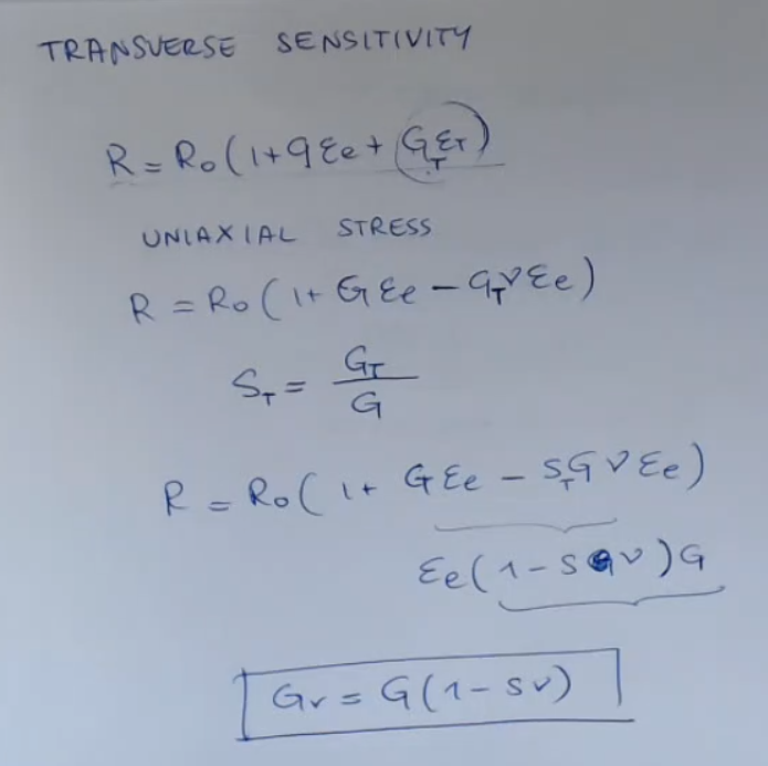
- is a factor to describe the transverse sensitivity, and is a ration between the transverse gain () and the normal gain ()
- So the guage factor in case of uniaxial stress along the direction, is resduce by a factor of , due to the transverse sensitivity of the gauge sensor (due to how the strain gauge is built).
It can also be wrote as:Where:- is the true value of the gauge factor.
- is the transverse gauge factor.
- is the Poisson Modulus
While in case of General Stress:
 I write it better:Which is identical to say:
Temperature Effects

~Ex.: Temperature Effects • Uniaxial Stress Case
Relative Variation of Resistance for Metals and Semiconductors
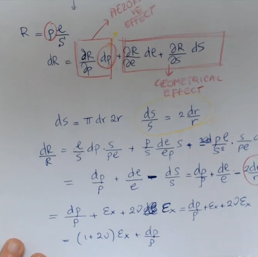
Resitance for metal strain gauges varies both with the piezoresistive effect, and the geometrical effect:

- This formula comes from the basic formula of resistance , and since to obtain a piezoresistive effect we need to exert a certain strain, se we change the lenght () and surface area () respectivly by an infinitesimally small factor of and .
So we can calculate the infinitesimally small variation of resistance () using the shown formula, basically by deriving it where: - : relative variation of resistance, or “fractional change in resistance”.
Where:- is the change in resistance.
- is the inital resitance value.
- : relative variation of resistivity (this is provoked by the piezoresistive effect)
Which is: - and : these are the relative variation of lenght and relative variation of surface area.
Instead for semiconductors only due to the piezoresistive effect:

- The basic formula: is true also for semiconductors, but this change in resistance can be negletcted since it is significantly smaller than its piezoresisity effect.NOT_SURE_ABOUT_THIS