Remeber:
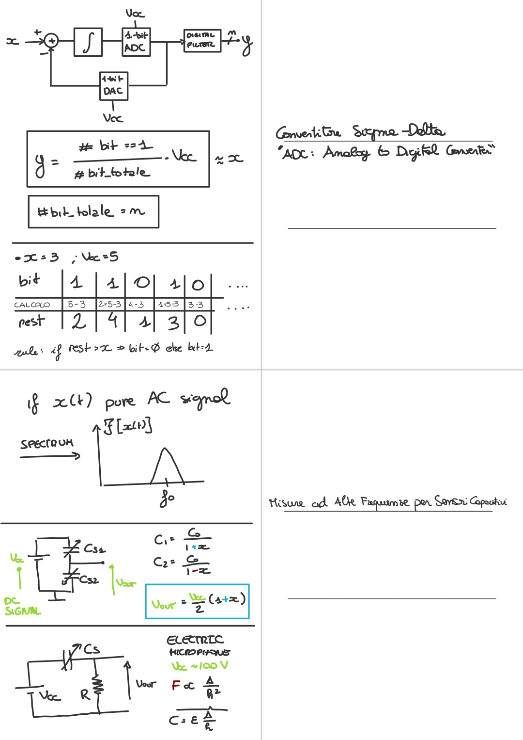
If the signal measured by a capacitive sensor has DC components, to “catch them” we need an AC exitation, as we have said before. While if we have a pure AC signal (meaning with no DC components), so it has a spectrum like this:
⇒ Then DC exitation is possible.
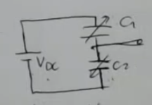
With a simple setup we can obtain the value of our measured quantity :
- The output will be, if we perform the calcualtions:Where: the offset can be corrected, and the final output can be amplifed and inverted.
We have seen the example of a capacitive microphone:
The measured value is very small, and the nedded force , to move the plate depends on: Where and are the physical dimensions of the sensors ⇒ the minimum force which has to be overcome to move the movable plate is really small.NOT_SURE_ABOUT_THIS So the needed DC exitation to get a readable signal would be really high, usually, it’s a large value ().IMPORTANTENOT_SURE_ABOUT_THIS
Memory Card
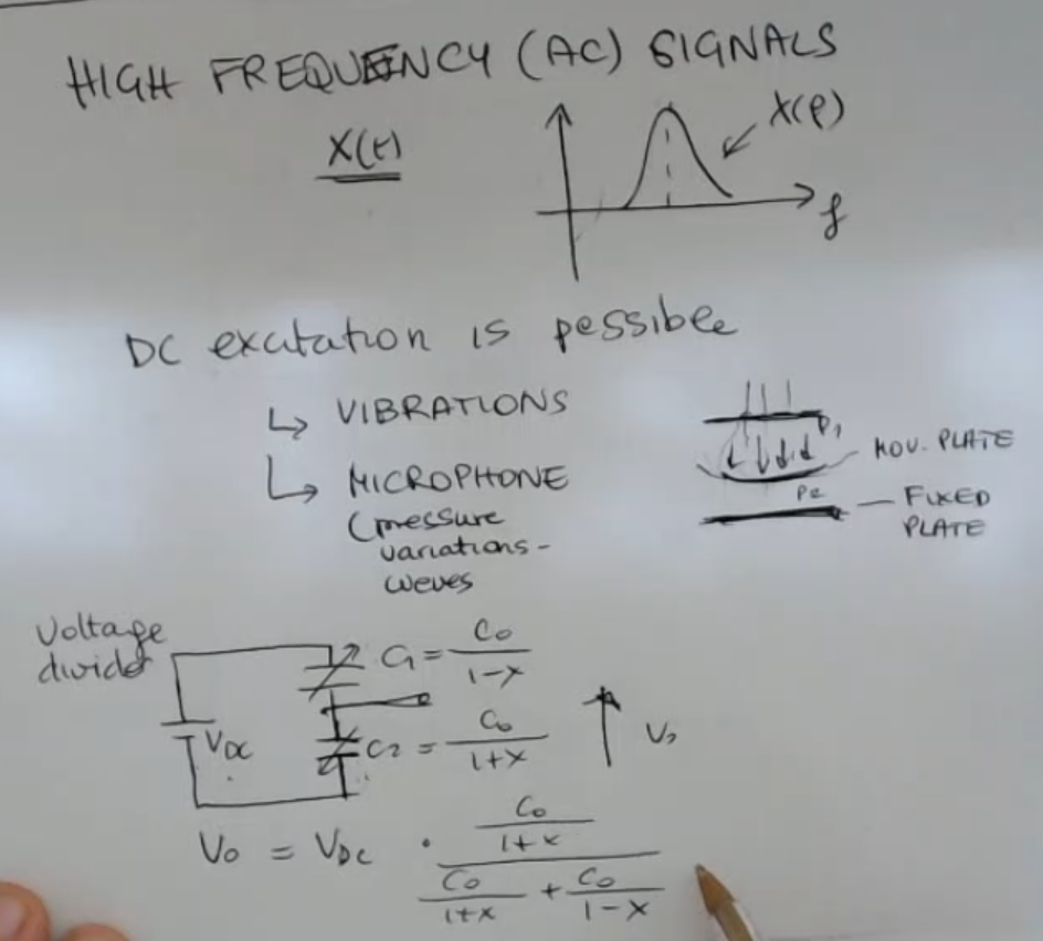
- When we deal with AC signals and usually high frequencies signals, which means that the spectrum of : , so if the sensor measure has no DC components.
⇒ Then DC exitation is possible. - While in AM and FM we had only AC exitation.
- A simple capacitive microphone uses this formula:
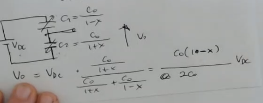
- With a simple voltage divider using two sensors with “opposed signs”, we have:
- Also note that the offset of can be removed, and the theoretical output value can become: Of course the output can be then amplified and inverted.
- usually, it’s a large value ().IMPORTANTE
Here we can see a typical solution in case of a capacitive microphone:
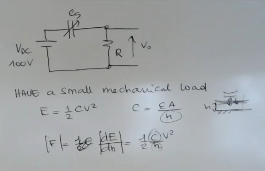
- Capacitive microphones have a small mechanical load represented by .
- Since the value is very small, and the nedded force , to move the plate depends on: Where and are the physical dimensions of the sensors ⇒ the minimum force which has to be overcome to move the movable plate is really small.