Index
- Applications for Capacitive Sensors (FM & AM Oscillators)
- FM Modulation Based on Oscillators
- AM Modulation Based on Oscillators
Applications for Capacitive Sensors (FM & AM Oscillators)
So, we spoke about capacitive sensors and about the main problem of capacitive sensors:
- We underlined that there is the need of using shields.
- We also underlined the difference between rounded sensors and unreferenced sensors because they admit different solutions, for the readout electronics
So now we will say something more about the readout electronics for capacitive sensors.
We distinguish two different applications for these sensors, the first is related to low frequency signal and it is the first one that we will discuss.
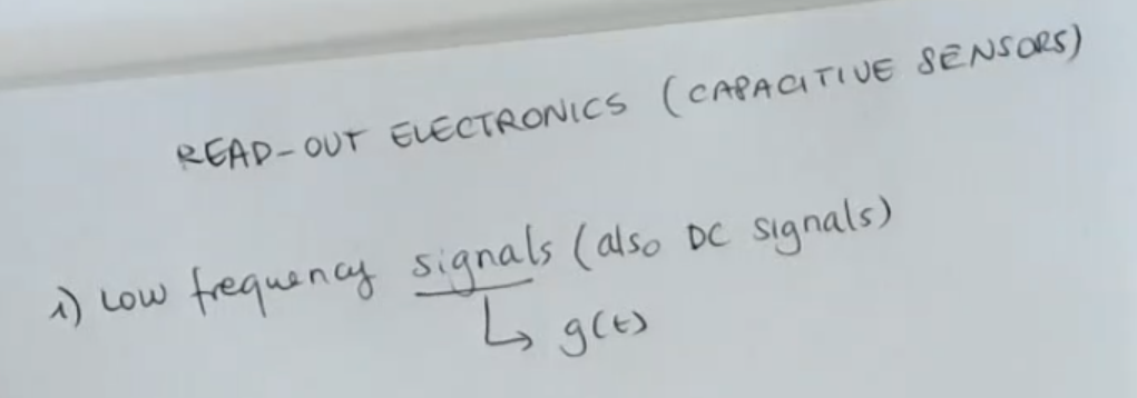
First of all, we’ll speak about the case in which capacitive sensors are used to measure
low signals or static signals.
- So the quantity that it is sensed by the sensor is a slow varying signal, this signal here is referred as so the input of the sensor.
- We will have a sensor which transduces this quantity into the capacitance.
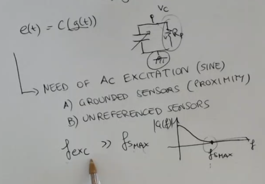
So our sensor will give us , where:- : output of our sensor
- : means that the output will be a capacitance depending on
- : input of the sensor
- So in any case this signal here varies slowly, and what happens is that the capacitance takes a value which is constant for a long time.
This time is enough to allow the loss of the charge which is stored in the capacitors due to the parasitic resistances.
==Remember that when thinking to a capacitance, we also have to imagine that there is always this parallel resistance: ==.
⇒ In this case we need to vary the charge by exciting the capacitance with AC excitations (so a variable excitation), so will be an AC exitation (for simplicity a sine wave).
Also the frequency of the excitation () has to be selected, and it has to be much larger than the maximum signal frequency (). - Remember that for capacitive sensors, we have to distinguish always between:
- Grounded sensor, (remember about proximity sensors).
So this kind of sensor which has the requirement of having one of the two terminals referenced. - And the other type are a referenced sensors.
In this case we are completely free to choose the best readout topology, because we have no constraints about the grounding of one of the two terminals.
- Grounded sensor, (remember about proximity sensors).
Under all these assumption we can find two types of readout electronics:
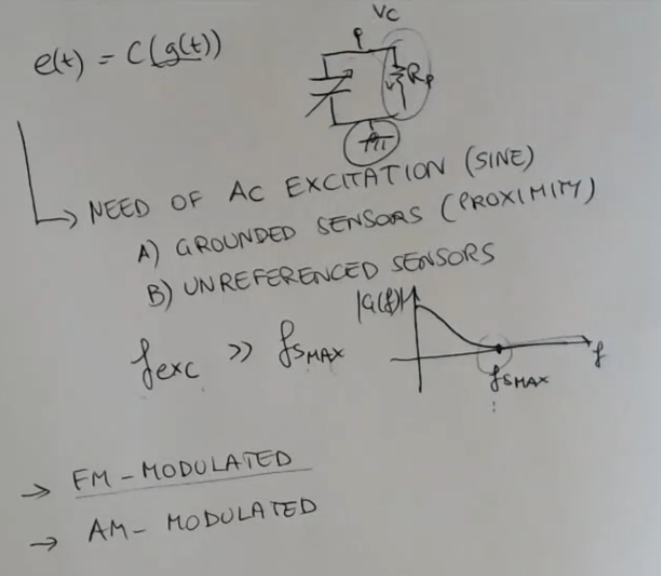
- FM modulated:
So these are circuits which are based on a strategy which considers the frequency modulation of the signal. - AM modulated:
We will understand immediately what it means.
FM Modulation Based on Oscillators
FM : Frequency Modulation
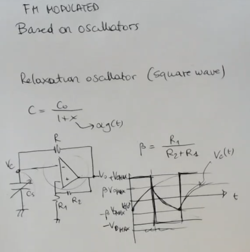
- This type of circuit are based on oscillators.
- So I take an example, which is a special oscillator called relaxation oscillator, which actually is a square wave oscillator.
- The AO in this case works as a comparator.
- In this circuit the time (or period) it takes for the output to switch from to is a function of the sensor’s capacitance .
So to get the sensor value we need to:
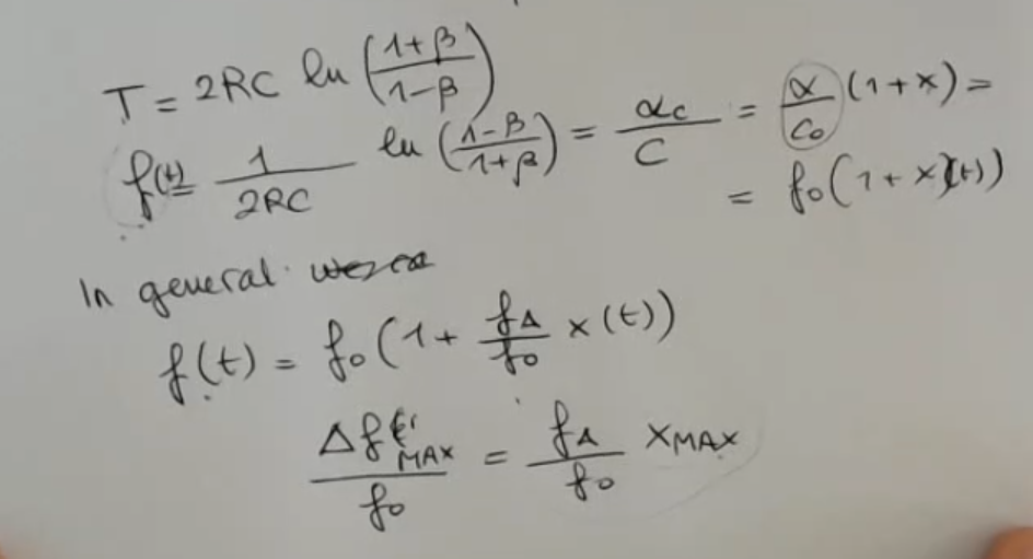
- So our sensitivity and offset are both equal to:
- Where:
- Also we previously have defined as , where is the varying part, as it is the sensor’s capacitance it can change.
- Also more in general we can say that the Frequency of an FM Modulation can be defiened as:
- represents a fequency (it was defined as the inverse of the period )
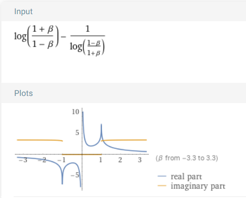
NOTE: In the notes there is a WRONG simplification: As you can see this is wrong, (if it was right the real part, in blue, should be all equal to , and there should not be an imaginary part):
So in general referring to the sine wave, we have an output which is this one:
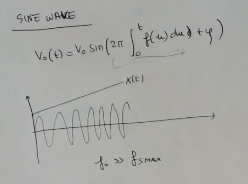
- : our target signal (what we want to measure).
- We can have a phase if we want to, but it’s not so important.
- The frequency and the phase are variable with time.
- ==If for instance if I have which is a slow invariant signal, then the frequency would start at a low value and then increase and increase and increase==.
- The requirement of having , indicates that this variation here is much slower than the variation of the basic signal, it is like the excitation signal is complex.
- Why the Integral?:
- The reason is purly mathematical, but to understand let’s make an example:
Suppose the signal does not vary, so the voltage should be somenthing like:Tho it may vary.
If it does, we need to account for each little, infinitesimal, variation, to do so we need an integral.
- The reason is purly mathematical, but to understand let’s make an example:
So this is a frequency modulated signal and we know that the bandwidth that we obtain is infinite, but if the maximum frequency of the signal () is much smaller than the base frequency () then we can approximate in this way the bandwidth of the FM signal which is: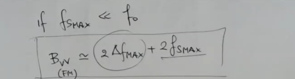
- Where:
- .
- And comes from:
- The complete FM circuit has this topology here: …
- We can say that this kind of readout electronics, since it transforms a variation of the input quantity into a variation of frequency is a very robust solution to reject noise.
- What do we mean with bandwith of a signal?
- The bandwidth of a signal refers to the range of frequencies contained within that signal.
In the context of signals, such as audio or electromagnetic waves, it represents the difference between the highest and lowest frequencies present in the signal. - Mathematically, the bandwidth ((B)) is often defined as:
- Where:
- is the bandwidth.
- is the highest frequency component in the signal.
- is the lowest frequency component in the signal.
- For example, in the case of an audio signal, if the lowest frequency is Hz and the highest frequency is Hz (or kHz), then the bandwidth of that audio signal is .
- Understanding the bandwidth of a signal is important in various fields, including telecommunications, signal processing, and electronics, as it determines how much information the signal can carry and how it can be transmitted or processed efficiently.
- The bandwidth of a signal refers to the range of frequencies contained within that signal.
The complete FM circuit has this topology here:
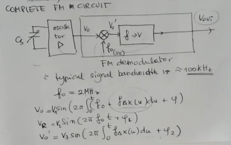
- The sensor which is part of the oscillator, as we have seen previously.
- is the function that previosly we defined as
- Note that has no “frequency offest” , it was removed thanks to the signal .
- The FM Demodulator has the job of giving as output a\kern2px voltage related to the frequency in input.
- This kind of solution is used for signals which can be static but also they have a large bandwidth up to .
- the typical value for is (much larger than the maximum signal frequency).
AM Modulation Based on Oscillators
AM: Amplitude Modulation
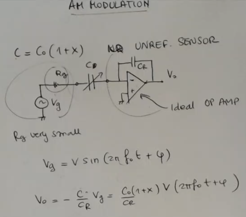
- This time we define , and it has to be an unreferenced sensor.
- : reference capacitance
- and : AC source and resistance.
is considered to be very small so I will neglect it from now on.
In practice this means that we have to take a good voltage generator. - And we have seen that this is a good solution because, in terms of sensitivity to electrical noise.
- is the excitation frequency, so I select it arbitrarily.
- The output function is a little wrong:
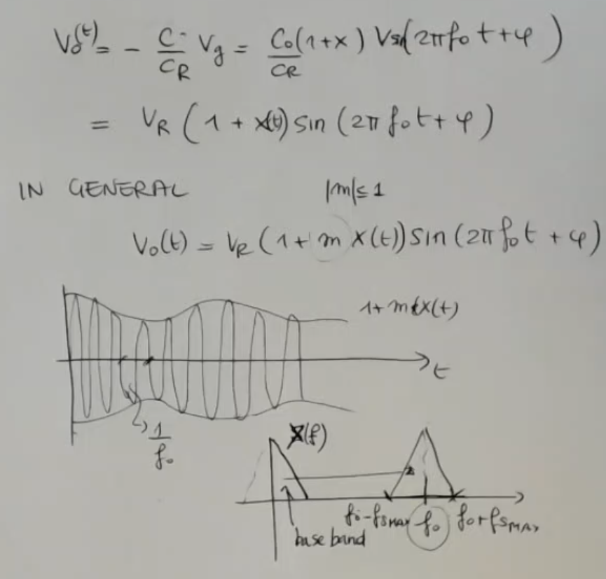
- So in general, using solutions like this in which our capacitance is a part of the gain of the circuit (of the amplifier) with a topology selected in the particular case to be suitable for this situation.
- is usually less than 1, like before (in the FM we called it to enfasize that in FM we talk about frequency, in AM about amplitude, they should both represent the sensitivity of the capacitive sensorNOT_SURE_ABOUT_THIS ).
- Here the bandwidth is easily found, so the description of the signal in the frequency domain is easily found.
- If this was the spectrum of the signal base band, the original spectrum, then the modulated signal is this one, and it’s frequency shifted, obviously by the modulation process.
From the spectrum we understand that if this frequency is much larger than the value of the maximum frequency of the signal , then the recover of the signal is easier.
Instead, if this is more close to the frequency of the signal, then there will be difficulties in the demodulation process.
And so we can list a certain amount of circuits, which are good for this application:
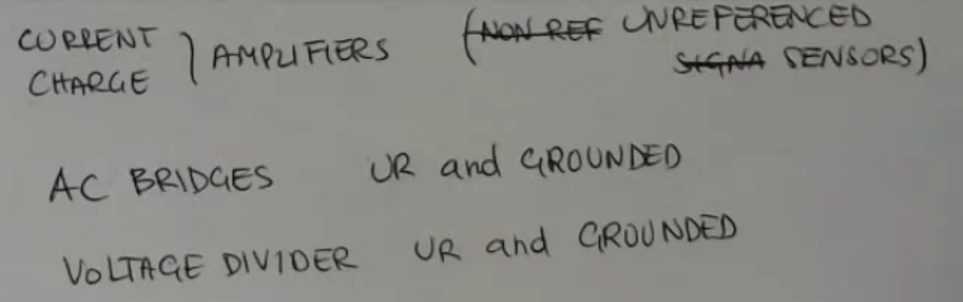
- Current or Charge Amplifier.
And this obviously can be used with unreferenced signals and sensors. - AC Bridges.
Like we have seen the resistance bridges, we can form bridges with capacitance and resistances.
This is good for both referenced sensors and grounded ones. - Voltage Divider:
Which can be used with unreferenced and grounded ones.
So for the complete AM circuit, I’ll do two examples, one for differential capacitance sensors:
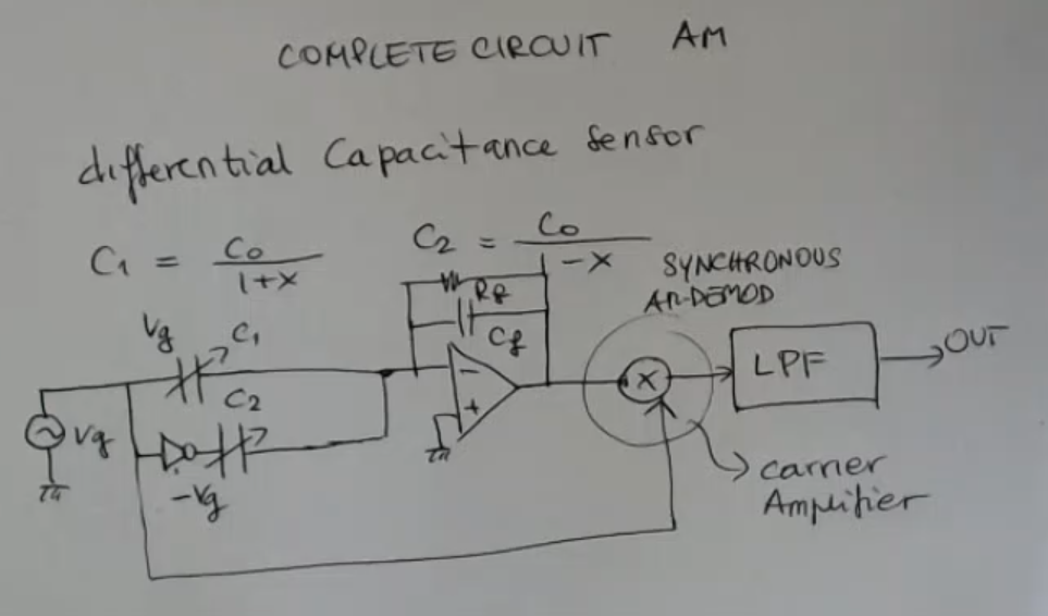
- Note: this is an inverting amplifier.
- So differential because the capacitances are:
- : needed to reduce the effects of DC errors of the amplifier.
- And then we can perform a synchronous AM demodulation (for instance, a charge amplifier), then low pass filter, and finally the output.
Summary of AM and AF Modulated Circuits
We have seen AM modulated circuits, FM modulating circuits.
Then we have seen two special types of readout front end circuit, which is the direct digital capacitive conversion and the switching capacitor circuit, these can be used for static signals, also for signals which are slowly varying.
Then some of these is more suitable to be used also for signals which have large bandwidth and other instead for really slowly varying signals. But in any case, they can be in principle used also for static signals.