List of things to memorize:
SaM - Inductive Sensors
Link to original
- SaM - Magnetic Lumped Parameter System • Electro-Motive Force • Variable Reluctance
- SaM - VRS (Variable Reluctance Sensors)
- SaM - Eddy Currents • Eddy Probe
- SaM - Different Solutions for Contactless Probes • Inductive Senors vs. Capacitive Sensors
- SaM - LVDT Sensor (Linear Variable Differential Transformer) • Transformers • Magnetic Induction
- SaM - 5 Wires LVDT (Linear Variable Differential Transformer)
- SaM - Hall Sensor
SaM - Magnetic Lumped Parameter System • Electro-Motive Force • Variable Reluctance
- They usually give a very large output signal.
- They are also robust.
- Lumped parameter:
- Effort quantity: (Magneto Motive Force) (ampere turns, since it is found multipling the current per the number of turns of a inductance).
- Flow quantity: (Flux of the Magnetic Field) (volt seconds).
- Basic structure of a magnetic circuit:
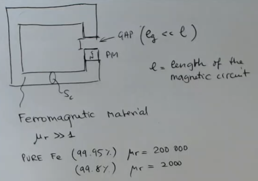
- Magnetic field lines, and powered coil
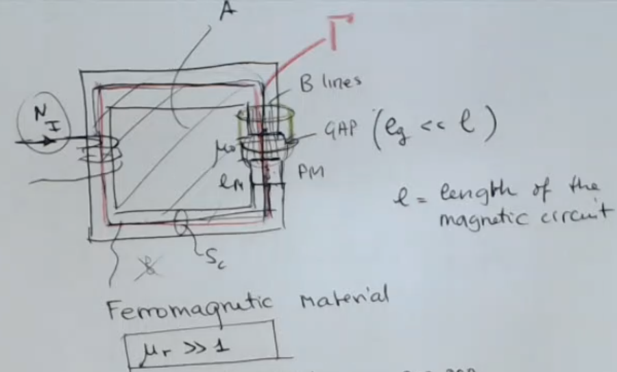
- Lumped parameter system, with no PM:
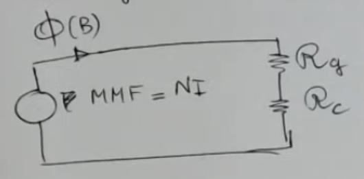
- Formulas:
- Lumped parameter system of the powered coil
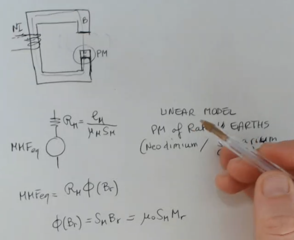
- Formulas:
- Complete lumped parameter system:
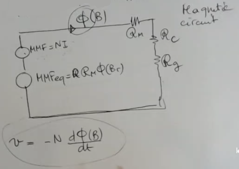
- Electro-motive force formula:
- Terminology:
- : length of the gap.
(The pedix will always refer to the gap) - PM: Permament Magnet.
(The pedix will always refer to the permamanent magnet) - : surface of the core.
(The pedix will always refer to the core) - (permeability of the core).
- is the magnetic field intensity .
- .
- is the magnetization
- is the magnetic susceptibility.
- : length of the gap.
SaM - VRS (Variable Reluctance Sensors)
- Basic strucuture for an active VRS:
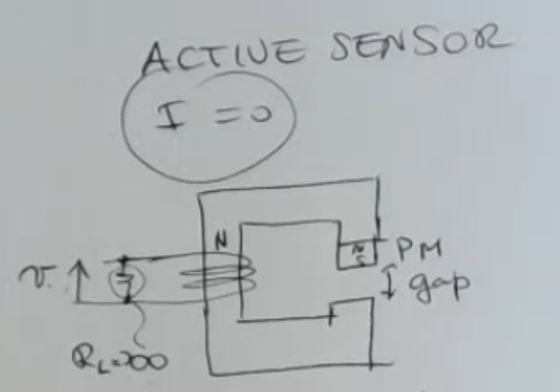
- Formula:
- Example for a speed VRSensor:
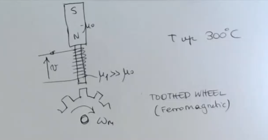
- Its lumped parameter system
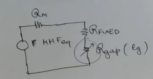
- Formula:NOTE: depends on which changes, it is NOT a linear sensor.
- Plot:
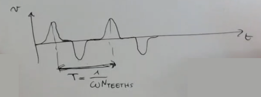
- Period:N.B.: the amplitude of the graph will scale with , not just the period.
This can be a problem, because we will have a good signal to noise ratio (SNR) when the machine is rotating fast, and a lower one when it rotates slow.
==If the machine is still the only thing I will measure will be the noise==. - Terminology:
- is the electro-motive force (this is actual voltage measured in Volts, but has sign inverted with rispect to the actual voltage drop).
- : equivalent magneto motive force.
- : total reluctance
- : non-specified constant. NOT the sensitivity.
- (previously called ) is the angular velocity.
- : number of theets.
SaM - Eddy Currents • Eddy Probe
- Conductive, non-ferromagnetic target, with a coil exited with Alternated Current (AC):
(In order to have a “measurable eddy current effect”, usually we use very high frequency )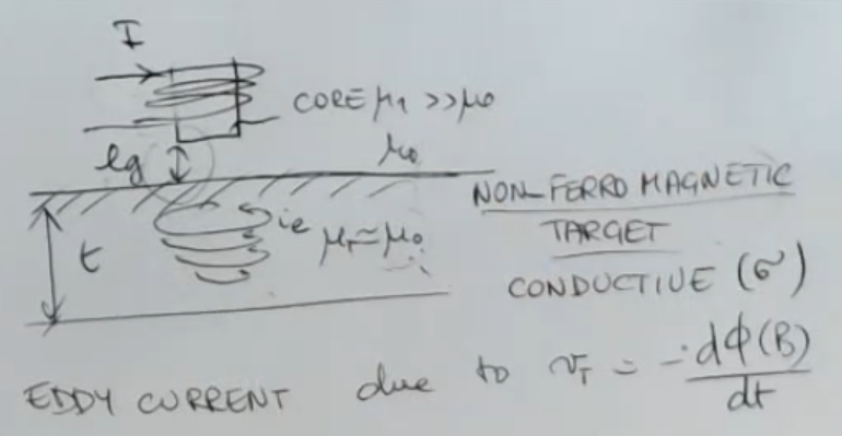
- The “Eddy current”, forms a magnetic field which opposes to the variation of the flux.
- Eddy currents probe can be used, but they need to be calibrated depending on the material (not good).
- Minum skin depth:
- Electrical equivalent cirucuit:
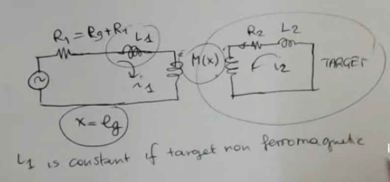
- Impedance formula:
(NOT IMPORTANT, too difficult) - Simplified formula:
- Real World Measures:
- Skin depth of various material, with :
- Alluminum:
- Permalloy:
- Steel:
- Equivalent percentage inductance , with different materials:
- Some materials increases their inductance , like Stell.
- While other decreases their inductance, like for example Alluminum.
- Also the percentange change of can assume values of around .
- Graph:
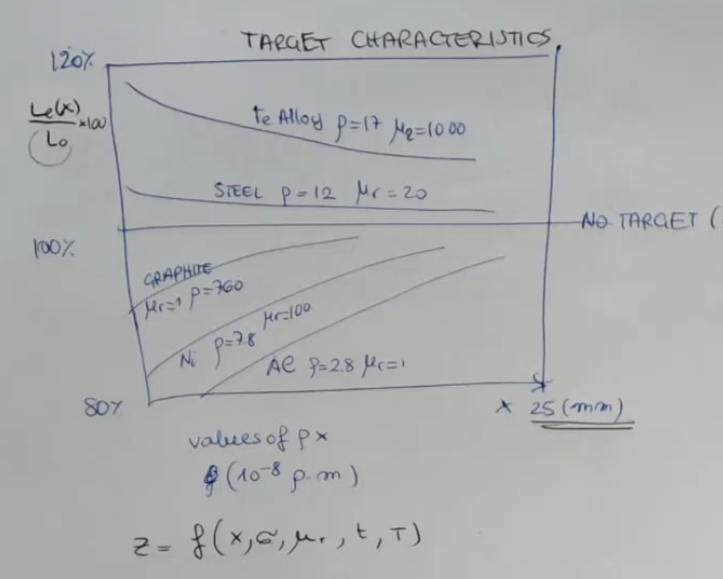
- Skin depth of various material, with :
- Terminology:
- : thickness.
- : penetration depth of the magnetic field.
- : the conductivity of the target.
- : frequency of the excitation.
- : permittivity of the target.
- : magnetic induction
SaM - Front End for an Eddy Probe
- This circuit uses an Eddy Probe, to represent it I use the symbol of the inductance with 2 lines in front ():
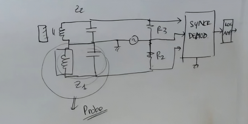
- We need a carrier amplifier, a synchronous demodulator, and a logarithmic amplifier.
- In this case, there is another probe (), which is not exposed to the target, it’s not facing the target, and it’s in an enclosed situation.
It is used only to compensate the temperature effect on the actual sensor, since the coil and also the resistance are sensitive to temperature.
SaM - Different Solutions for Contactless Probes • Inductive Senors vs. Capacitive Sensors
- Mechanical Load:
==Using common values the force exrted by a CAPACITANCE probe (using common values for , and all other parameters) is times less than than that need by inductance probe==, so usually:
Capacitive load:
Inductive load: - Range of Measurement:
For inductances (Eddy current), we can speak about a ratio of , which refers to range with respect to probe diameter.
For capacitances, instead, we have a range/diameter ratio.
⇒ ==So the longer range is obtained with INDUCTIVE solutions==. - Spatial Resolution:
What I sense is an average of the distance over a certain area, this area is called “the spot”.
For inductive sensors the ratio between the spot diameter and the probe diameter is .
While for capacitive sensors it is .
⇒ ==So if we want to measure the avarage distance in a large area we may opt for an INDUCTIVE solution, instead if our target is small we may opt for a CAPACITIVE one==. - Complexity of Front End:
==For capacitive sensor, the front end is far more complex==.
In fact, the INDUCTIVE probe gies large signals that don’t need particular care for conditioning, for noise and so on. - Complexity of the Probe Itself:
==For CAPACITIVE sensor, the probe is just a plate, it is far less complex than the inductive probe==.
The only problem for capcitive proximity probes, is to ensure there is an sufficient insulation between the plate and the shield and so on, so this is the only problem. - Environmental Conditions:
| Eddy currents (inductive sensors) | Capacitive sensors |
|---|---|
| : The target needs to have a minimum thickness. Also there is some restriction on target’s characteristic: (permeability) and (conductivity). The uniformity of the material, and the surface type. The target has to be homogeneous in order to be able to use the calibration that we have done with that specific material. ⇒ If you change material type or if you have a non-homogeneous material, then you can find problems. | The target is not influential, the target is uniformity is not influential, same for the target’s characteristics, surface roughness and so on, because we only need the target is conductive. |
| Then we have the possibility of having an external magnetic field which disrupts the measurement. | |
| And finally temperature. | Temperature is not influential, unless you go to very high temperature, which can change the directly behavior of the air or the gas in between being to plate, but this is in extreme condition (when becomes variable with temperature) |
| Tho if I place dirt, humidity, …, in between the probe tip and the target, if it has the same permittivity and is not conductive ⇒ then it doesn’t matter. ==For this reason, inductive sensors are robust for industrial applications== | Instead it is influential: dirt, oxidation of the plates, because it’s like placing the different direct there, humidity (sometimes) or condensed water (everytime), finally the electrical field is also influential for conductive sensors |
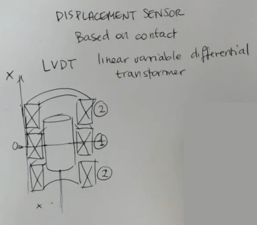
SaM - LVDT Sensor (Linear Variable Differential Transformer) • Transformers • Magnetic Induction
- Mutual inductance formula:\begin{align}&V_1 = j\kern2px \omega \kern1px M \kern1px i_2\\&V_2 = j\kern2px \omega \kern1px M \kern1px i_1\end{align}
- LVDT sensor structure:
- Electric circuit*:
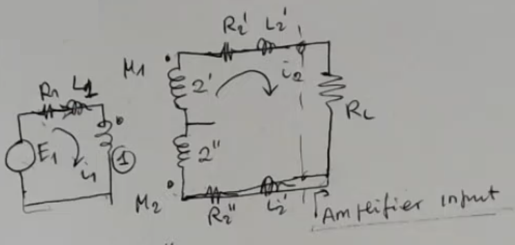
- Output formula:
- Bode plot of the relative sensitivity:
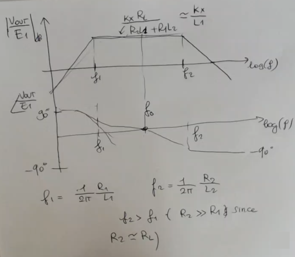
- Simplified formula, in the linear region:
(So: , ⇒ and )
(Like other sensors, this looses the sign of ) - Commonly we select , where:
- Output graph:
- Complete circuit, with sign-recovery:
- Terminology:
- (linear approximation).
- ==Remeber that this model is valid for ==, meaning that the mesurand must vary relatevely slowly to the exatitaion, so that we can consider constant to respect to the exatation signal .
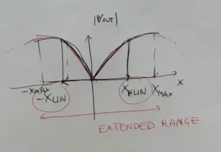
- We can approximate this sensor as linear if we stay in the “linear range” defined by .
But sometimes it is accepted to work in the extended range: .
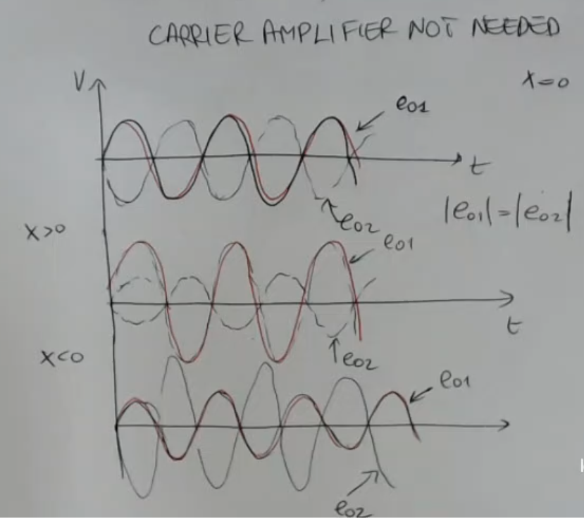
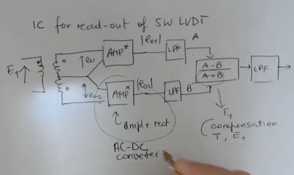
SaM - 5 Wires LVDT (Linear Variable Differential Transformer)
- Circuit:
(By adding a wire the carrier amplifier for sign recovery, is no longer needed)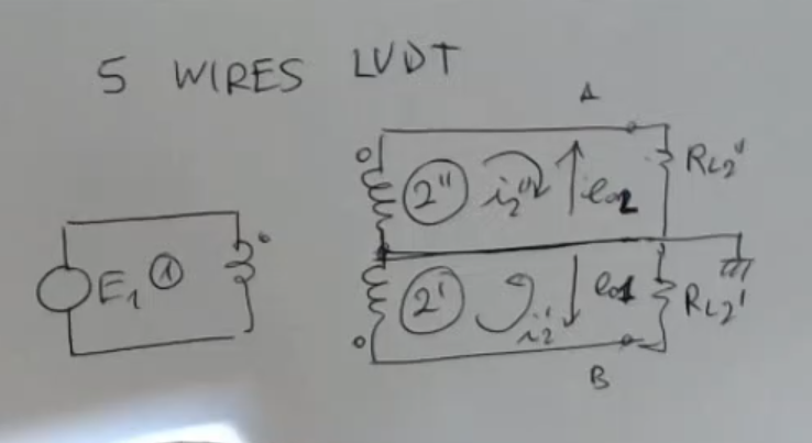
- Formulas:So:
- this time is a little more complicated and it is defined as:
So: - is the mutual induction of both and at rest.
- this time is a little more complicated and it is defined as:
- Output for , , :
- Complete circuit, with compensation for temperature and noise :
SaM - Hall Sensor
- Simple strucuture for the “Hall effect”:
(It must be a conductive material)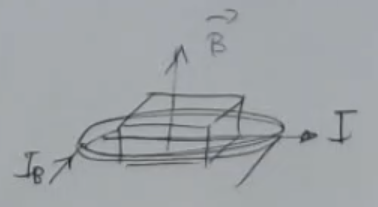
- Lorentz force formula:
- More complex drawing, with angles:
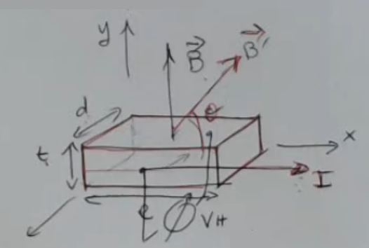
- Formula:Where: , so:
- Final formula:
- Real World Masures:
- This device can be used to:
- Sense a magnetic field (if I know ).
- As a displacement sensor (if used with a permament magnet, so that I know , and I also need to know ).
- To measure the angle (I must know , ).
- Current sensor (I must know ).
- Advantages of an “Hall sensor”:
- Easily intefrated (with read-out, current generator and temperature compensation).
- The whole package (with compensation) can be sealed.
- Insensitive to contaminants in the enviroment.
- Simple structure.
- Large ranges for magnetic fields , and large bandwith .
- Low cost device.
- This device can be used to:
- Terminology:
- : magnetic field.
- : thickness.
- : width.
- : lenght.
- : current in a solenoid, used to generate .
- : current flowing in the conductive material.
- : velocity of the free charge moving due to the current .
- : potential.
- charge of the electron.
- : measured voltage across the conductive material.
Measured perpendicular to . - : “Hall coefficient”.