Here is a scheme on how we can use a magnetic circuit, to make a proximity sensor, like so: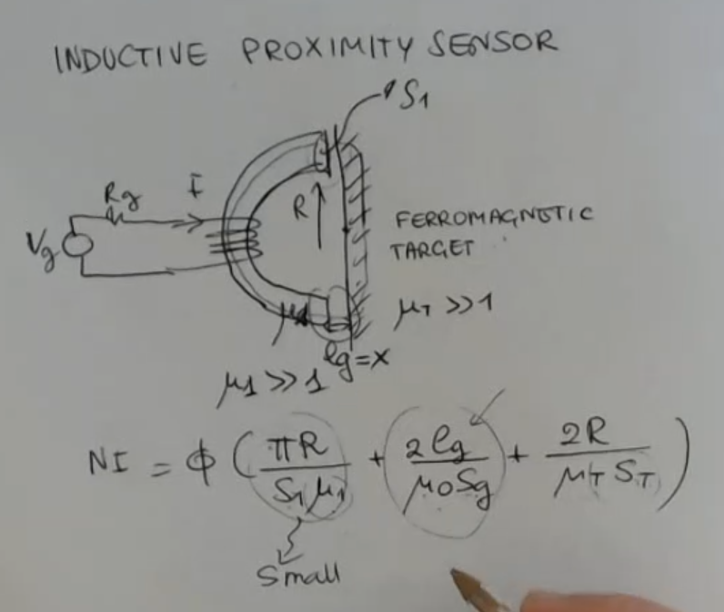
- We consider to have a ferromagnetic target.
- is the current flowing here generated by the electric circuit.
- The core has relative permeability , which is large.
- : the cross area.
- We expect that the flux line will develop with this geometry here, so:
- Half circle:
- Small gap:
- Straith line:
The inductance value will be:IMPORTANTE Here are the calculations:
(NOT IMPORTANT)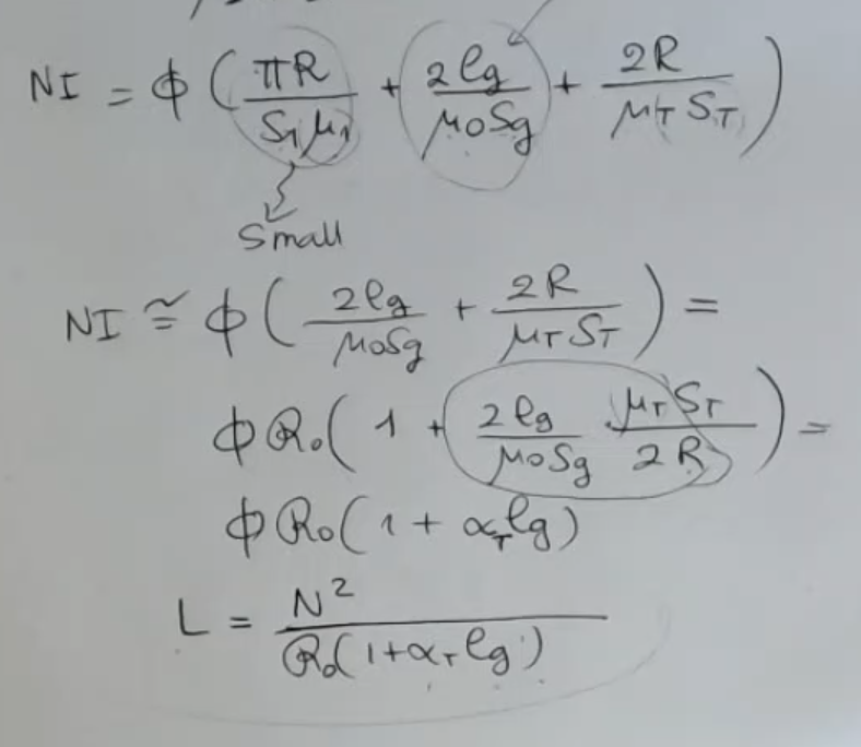
- So we have all these surfaces, which have the same magnitude order, but we have these two and , which really are reallyh larger than .
- so we expect to be the most important, even if , the order of magnitude of and is bigger.
The sensitivity will be:IMPORTANTE Where:
- : is fixed due to the sensor.
- and depend on the material, of the target.
⇒ So you see that the sensitivity this depends on the target, so ()
⇒ So you change the material of the target, you change the sensitivity.
⇒ The larger is , the larger is the sensitivity.
You can use the same arrangement to sense a variation of the reluctance due to the gap variation, ==even if the target is not ferromagnetic==, but in that case you will have really small sensitivity.
It’s quite similar to what happens for a capacitive sensor, ==but here I have a dependence on the material type==.
Here’s an example of how we can exite and read the sensor: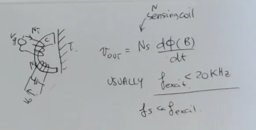
- I have an electrical circuit for exciting (), and another one for sensing, called “sensing coil” ().
- Using this setup, usually, the frequency needed to have a sufficiently strong signal are much lower than those used for capacitive sensing.
In capacitive sensing we have said that we use .
Here, usually since signals are larger, is less than . - Here’s a comparison between inductive proximty senors vs. capacitive proximity sensors