Remeber:
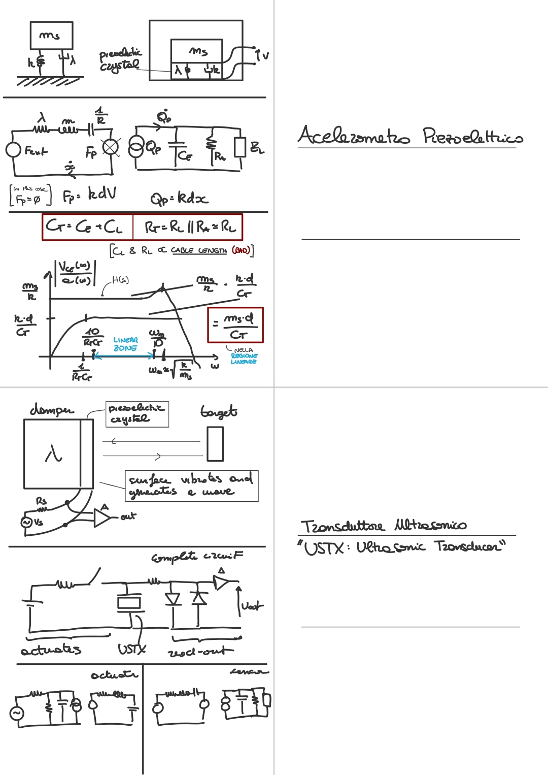
Here’s a basic strucuture for an ultrasound transducer:
- Structure:
- A piezoelectric slice of material (like quartz).
- An added dumper .
- A source voltage for exiting the piezoelectric.
- A read-out (an amplifier) to read the output from the piezolectric.
- Workings:
- We exite the piezoelectric, which is deformed inverse piezoelectric effect, and we make it vibrate.
- The vibration generates a wave.
- The wave bounces off the target, and returns to the piezoelectric, make it vibrate again.
- We measure the new vibration with the read-out.
- is usually a pulse:
This device can be used both as an actuator (it produces ultrasonic waves via the vibration of the piezoelectric crystal) or as a sensor (so as a sensor for ultrasonic waves).
This is reflected in its equivalent electrical circuit:
- USTX is the Ultrasonic Transducer, modelled just before.
- The two diodes are a protection circuit, for read-out part, it protects the amplifier when using the device as a transducer.
The two diodes cap the frequency that passes to the amplifier at around mV (this votlage is defined by the diodes).- This is the input-output voltage of this circuit:
Things to know about this device:
- There is a difference in the types of waves, depending on the type of target material:
- If we use an USTX on a linquid (or human tissues for biomedical applications), or in a gas we are talking about acustic waves.
- Instead if we use it in a solid we are talking about elastic waves
- Usual case scenarios are: biomedical applications, non-contact measure, NDT (non estructive testing)
- We usually use this device in “echo mode”, more on that later.
- This is a coarse approximation, since .
- We don’t have a sismic mass, what we are moving is the crystal, so now the mass is quite small, it’s only the mass of the crystal slice.
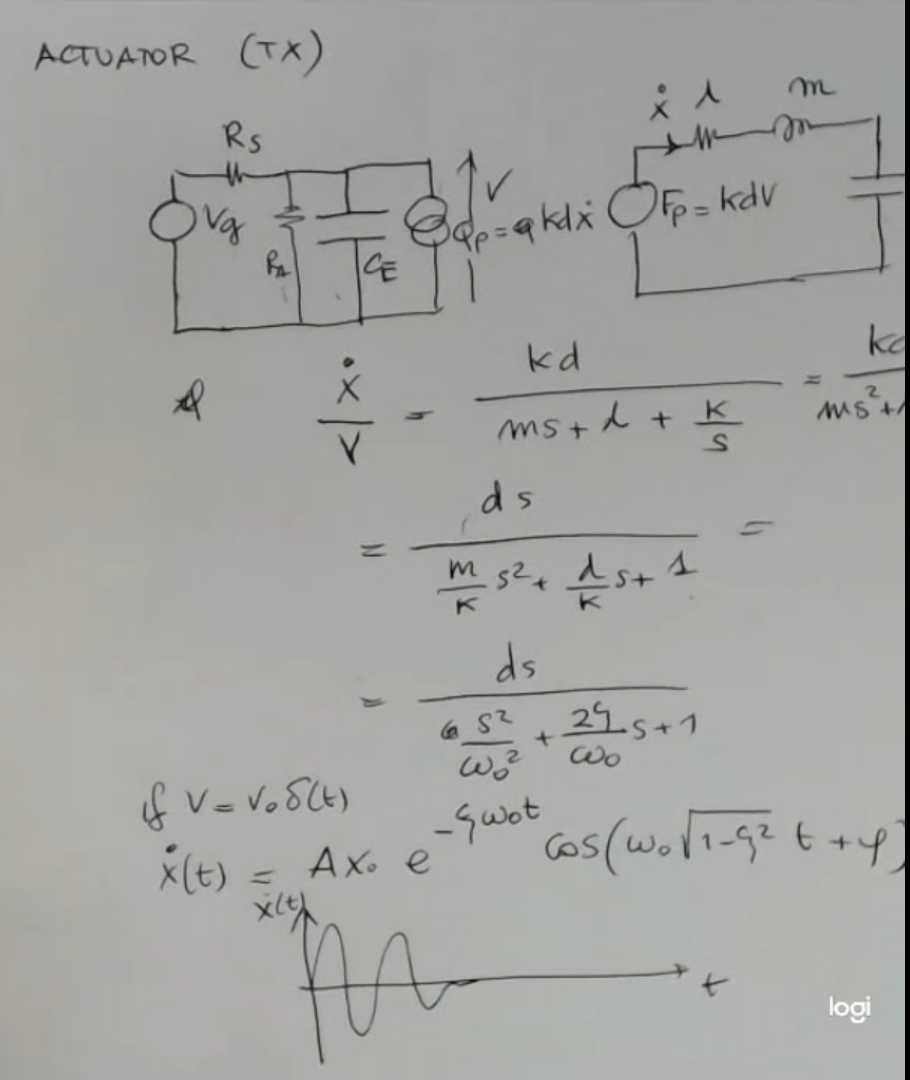
Here we can see the structure for when the ultrasonic transducers is used as an actuator.
So with connected, and both diodes ON:
- The piezoelectric crystall, or more specifically the USTX is modelled as a capacitance and a charge generator , also an impedance .NOT_SURE_ABOUT_THIS
- In more details we have seen the quartz oscillator.
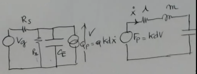
will have this simple form:
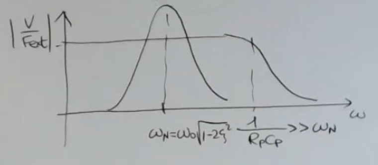
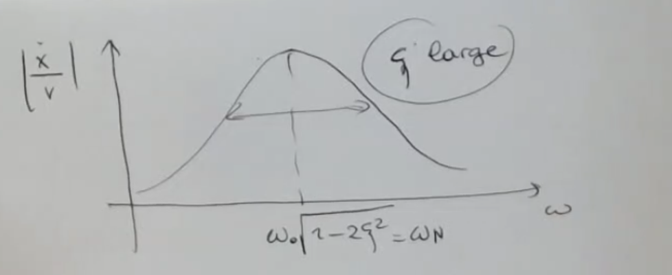
The formula is:And here if we plot :
- The width of the peak is related to the value of the , the smaller is , the smaller is this peak.
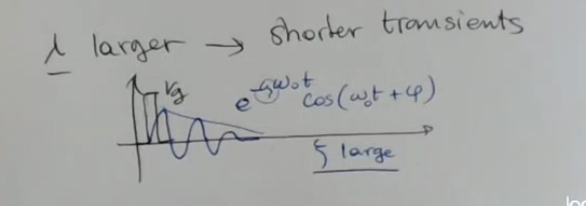
And if we have a large ⇒ we’ll have a large bandwitht, ==ultrasonic transducers are considered wide band devices==.- A large also means a short transient.
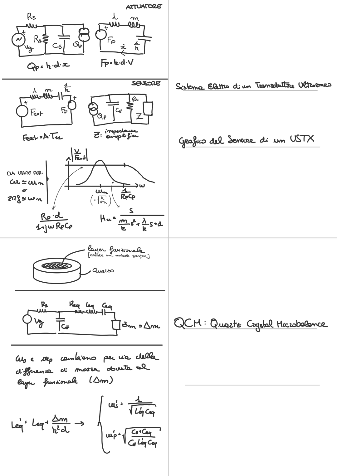
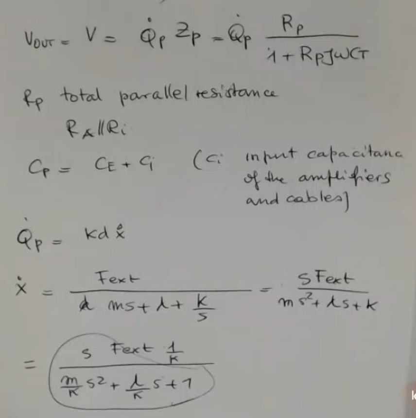
Here’s instead when it is used as a sensor.
So with disconnected, and both diodes OFF:The output of the transducer used as a sensor is a charge:IMPORTANTE Where:
- is the piezoelectric coefficient.
- is the elastic constant of the material.
- is the measured quantity, measured in .
The transfer function will be: Where:
- (impedance of the amplifier, usually a charge amplifier).
- found previously.
- found previously.
- And is the mechanical response:If we plot and :
- NOTE: It has the same equivalent circuit as the piezoelectric accelerometer, however the final graph (and formula) is different, in this case we use , while for the accelerometer we used , why?.NOT_SURE_ABOUT_THIS
- Then is the multiplication between the two.
- I write better:
- Remember: to find and we need to transform in its Bode form, and then we have: and .
In this case we have that: (like many other times) and (NOT IMPORTANT).- is defiend by the amplifier, and if it is designed well (so ) it will not distort the sensed value, it will only amplify it.
- NOTE: That the external force is given by the bouncing wave created by the crsytal (in case of echo-mode)
- ==So it is a resonant device in any case, which needs to be excited at the frequency close to its natural resonance==.
- An ultrasonic transducer device can be used in echo-mode, first we send a signal by using the device as an actuator: we induce the crystal to vibrate with an AC exitation, and then we use the same device as a sensor, to sense the bounginc waves.
- In any case, if we don’t operate in echo-mode, so we transmit a wave with a device and we receive the wave with another device, it is important to match the two devices.
==They must have the same resonant frequency in order to be able to use them together==.
Memory Card
- Ultrasonic transducers are intended for generating and receiving ultrasonic waves.
Ultrasonic waves are pressure waves in fluid or stress/strain waves in solid, which can propagate through solids, can be reflected by obstacles and go back to the transducer to be received. - So ==this kind of device is actually both an actuator and a sensor==.
- And mainly this kind of transducer are used in echo mode, (we’ll see more detail later) in order to sense the generation from distant targets
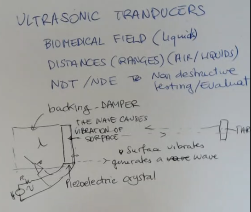
- The applications of ultrasonic transducer are mainly in biomedical fields.
And in this case, we consider the wave to propagate in a liquid, because human tissues can be seen as mainly as liquids. - They can also be used to measur distances, obviously non-contact, and in this case, usually it’s in air.
so mainly they are used in in air or liquid. - Finally, there is also an application in the so-called non-destructive testing or non-destructive evaluation, and in this case, the waves propagated in solid media.
- NOTE: this device also has a backing/dumper, this will increase the value of the dumping coefficient as we will see in the lamped parameter system.
So the ultrasonic transducer structure is similar to the one of an accelerometer, but there is a difference, which is this:
- We have the crystal, the piezoelectric crystal, which is induced to vibrate, for instance, from an external generator.
- By vibrating, the surface vibrates and generates a wave, which propagates in a medium.
- If the wave founds a target, the wave is reflected.
- The reflected wave goes back to the surface, it exert stress over the surface, a pressure in the liqui, so it induces a new vibration, an echo if you will.
- Now the same crystal is used as a sensor, and is able to detect the echo, by detecting/sensing a vibration on the surface and translating this vibration into an electrical signal (like how we have seen before).
The difference with respect to an accelerometer is that in this case, we don’t have any seismic mass.
If we go to the mechanical equivalent circuit:
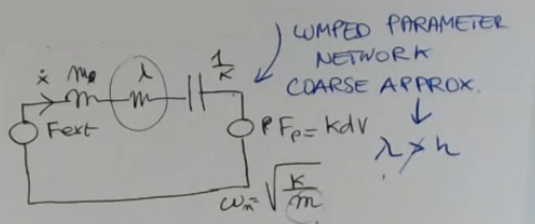
- We have the same , which represents the elastic behavior.
- The damper is larger because there is this added element.
- Whereas the sensor mass, I cancel this pedix (previously seen when talking about the seismic mass ), because we don’t have a sismic mass.
Also now the mass is quite small, it’s only the mass of the crystal slice. - This kind of devices has to operate at larger frequency, with respect to piezoelectric accelerometer.
- The transient of this mechanical device is shorter, ==larger means shorter transient==.
Therefore, if this generator gets, for instance, a pulse, a shock, a delta function, then the transient response will be a short pulse and not a long one. - This is really a coarse approximation.
So we will use it, but take into account the results we find, which can give us an idea of what happens, are largely inaccurate.
Since in this case (usually) we don’t have that the wavelength of the mechanical wave (, unforntunately has the same letter as the dumping coefficient), so the displacement field is NOT larger than the dimension of the crystal ().
So ⇒ coarse approximation.
So if this is , then we expect a mechanical output, which is something like this, with a short duration:
- So usually they are, let’s say, wide band devices.
Another thing is the name “ultrasonic” means that we are operating at frequencies within in general are higher than the frequency of the sound.
This is the reason why we speak about high frequency vibrations and high frequency devices.
We have seen that it can both generate and receive:
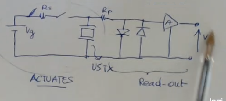
- The USTX is the UltraSonic Transducer, actually this part reperesents the crytsal, which we have just modelled.NOT_SURE_ABOUT_THIS
- Around the reciver there is a protection circuit, which protects the amplifier when using the device as a transducer.
- Note the switch after , when it is closed the sensor is used as an actuator, while when it is opened it is used as a sensor, and its output gets amplified by the amplifier.
- The two diodes cap the frequency that passes to the amplifier at around mV (this votlage is defined by the diodes).
They are used to keep this input to a voltage lower than beyond voltage of the diode.
== is “protected” by the diodes==.
I can find the vibration of the surface as a function of the voltage, which also depends on the frequency (as always):
- Lastly we simulate what happens with a pulse or step input (so )
If we plot it:
- The width of the peak is related to the value of the , the smaller is , the smaller is this peak.
And if we have a large ⇒ therefore we have large bandit.
After having finished this generating part, then the same device can be used as a sensor.
Therefore now this switch here is disconnected, and we have:
- As always can be regarded because usually this is larger but in any case it will be here, no matters.
- The two diodes are now off (open) because the signal now is very small, (it is the received signal), so we can neglect their existence.
Some calculations:
- We have used some different terms from before: and NOT_SURE_ABOUT_THIS
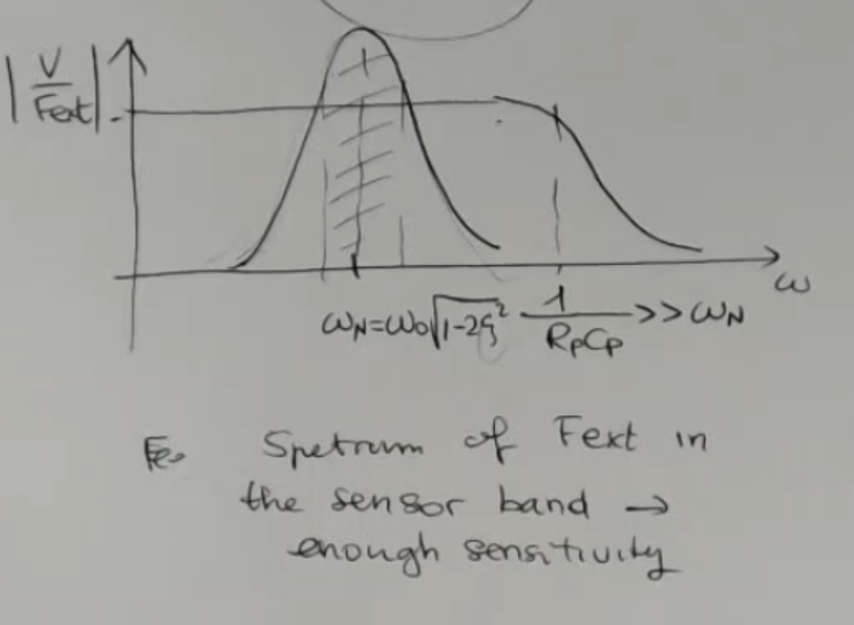
So we can go back here and call this function “ultrasound in frequency domain”: , so: If we plot it:
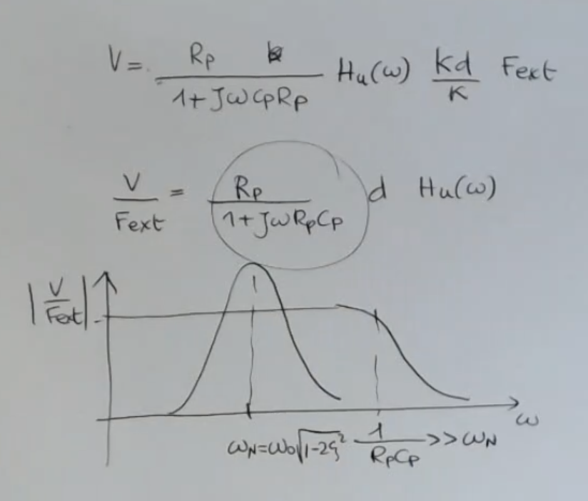
- Here we have two plots, the one is the plot and the other the plotted for , the complete plot is the multiplication of the two.
- The is the mechanical response.
- While is the electronic response.
- is the cutoff frequency of the (ideal) amplifier, and if it is designed well (so ) is will not distort the sensed value, it will only amplify it, (for frequency in which the device can be used around )
- The overall transfer function is resonant because of the large value of the damping.
We need that spectrum of external force to be in this range here in order to have a good response.
NOTE: That the external force is given by the bouncing wave created by the crsytal (in case of echo-mode)
- ==So it’s like a tuned device, a resonant device in any case, which needs to be excited at the frequency close to its natural resonance==.
- And in this case, we are analyzing which is the Echo-mode operation, whether the center is used both to excite the wave and to receive the wave.
- In any case, if we don't operate in echo-mode, so we transmit a wave with a device and we receive the wave with another device, it is important to match the two devices.
They must have the same resonant frequency in order to be able to use them together.