Remeber:
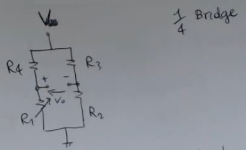
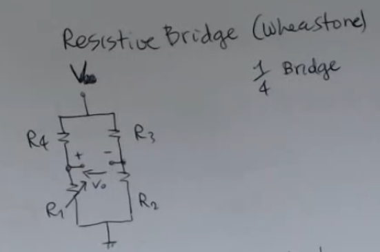
A resisitve bridge or “wheatstone” or ” bridge” has a structure like this:
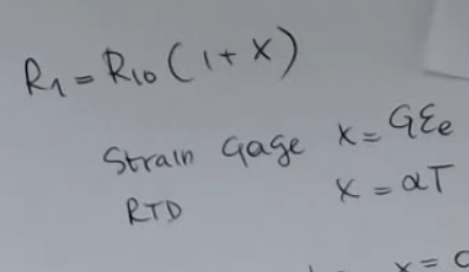
- is our sensor, and we will describe it with the formula:Where, based on the sensors we have seen so far can be seen as:
- , if we consider a RTD sensor.
- , if instead we consider a metal strain gauge.
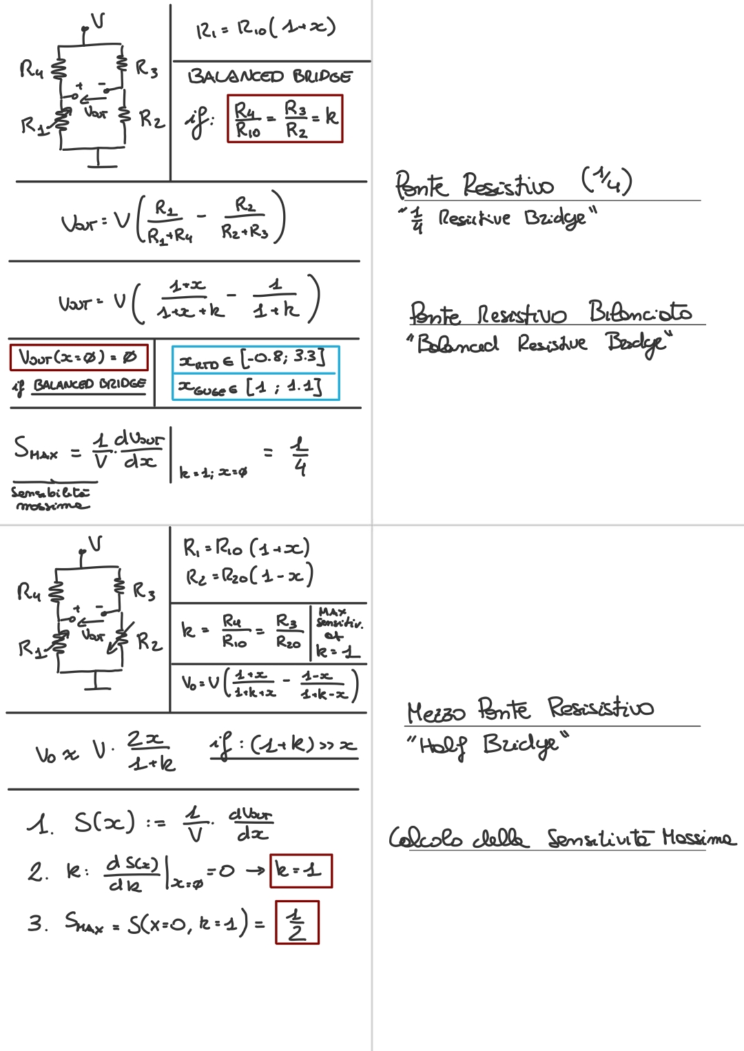
- The output of a ” bridge” is like so:So a resistive bridge will have a DC offset equal to: .
And a changing part (given by our sensor) equal to:
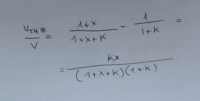
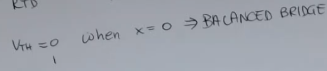
We can then define a particular resisitve bridge called a balanced bridge, that has the property that ==for the outptut will be ==. To achive this we just need to define the -ratio:Then the output will be:
IMPORTANTE The output is not grounded, this means the for the read out electronics for a resistive bridge we will need a differential amplifier. (In general we will need a read-out with at least two inputs).NOT_SURE_ABOUT_THIS We CANNOT use a one-input amplifeir.
We have also seen two variations of resistive bridges: half brige and full bridge.
What is the use of a balanced resistive bridge?
- If we were to measure the resistance of a strain gauge the formula, as we have said would be: .
In a real world scenario:
- The voltage assumes values in the order of
- And the variation of is around , so the variation due the strain is really low.
- While for RTD sensors, specifically we have seen the PT100 sensor:
- .
- , based on the range of temperature .
- For startets, at rest the output will be:
- For the normal passive sensor .
- For the resistive brige: .
⇒ The bridge corrects the DC offset of the passive sensor.- So the range of values can assume are quite limited, especially for strain gauges, to increase this range, we can use a resistive bridge with a “high” source voltage , so that if we consider the sensitivity, of the output value around , with , and we will have:NOT_SURE_ABOUT_THIS
- For the normal passive sensor .
- For the resistive brige: , so .
- ==If we use a balanced resisitve brige, we will also compensate for temperature, since changes in temperature will affect all the resistors in the bridge equally, maintaining the balance==.
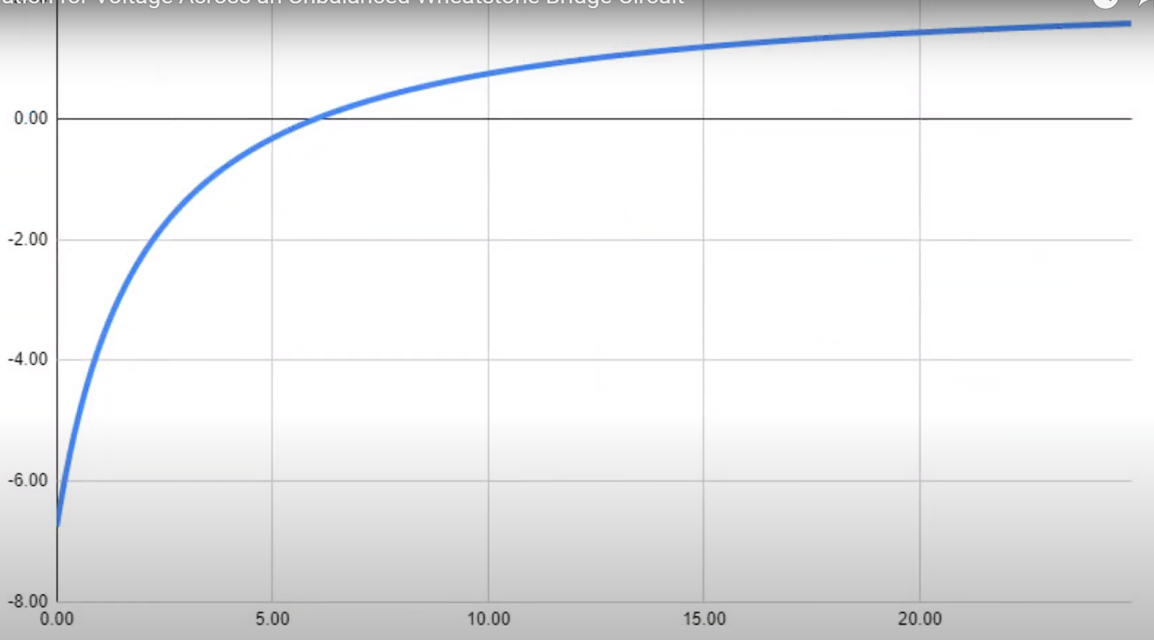
- However note that the resisitve brige, results in a non-linear sensor, if we plot how changes given , we will obtain somenthing like this:
Sources:
- Youtube ’# Basic configurations #1 - Wheatstone bridge’ (best explenation)
- Youtube ’# Why you need a Wheatstone Bridge to get accurate Strain Gauge Readings (simple fast explenation)
- Youtube ’# Wheatstone bridge & its logic | Electric current | Physics | Khan Academy’ (calculations)
Memory Card
If we do a thevenim equivalent we find:
And:
We can then divide in DC offest () that is all component that do not depend on (our sensor), and actual sensor component, all those parts that depend on :
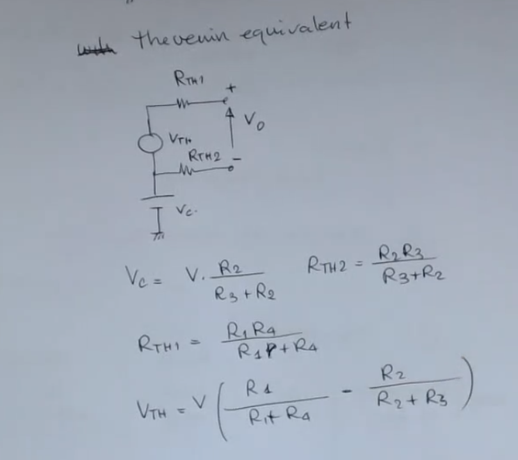
- and depend on
- While and are constant.
If we attach a Differential Amplifier to :
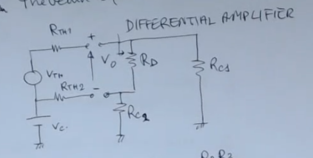 If Ideal:
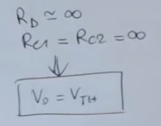 Otherwise:
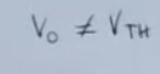
The generator represents the DC offset of your circuit: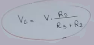
As we have seen, we can define as:
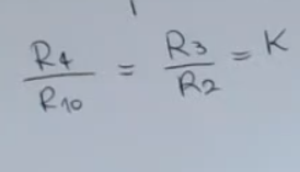
We define a “balanced bridge” if this condition is met:
We define the ratio:
And now we calculate the dependency of (the output) on the resisitances:
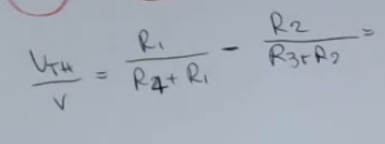 We perform a simple transformation, using:
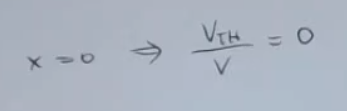
So if as we have anticipated we have:
You can see that this () is not a linear relationship:
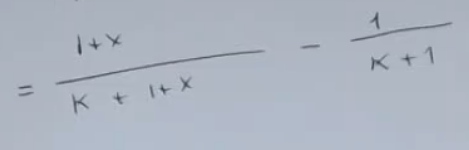
We can also define it in a more confininet form: