Remeber:
The structure is the same, a simple sismic mass accelerometer with a spring dump system:
- However the spring is made up of quartz, or more generarly of a piezoelectric layer.
- The two surfaces above and below the piezoelectric layer, are covered by a conductive layer, each surface is connected to a wire and this two wires are brought out of the case.
This way like for all piezoelectric sensor we have created a capacitance, from which we can measure the stored charge, usually by using a charge amplifier.- The mass of the crystal usually can be neglected, and the mass of this primary sensor coincides with the seismic mass.
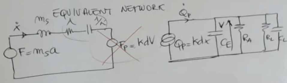
- Here’s the equivalent circuit:
- We can neglect , since this force is usually so small, very small with respect to (the external force).
Output formula:Where:
- : natural frequency
- is the spring consntant of our accelerometer, and the sismic mass.
- == and depend on the wire’s lenght (bad)==.
- : laplace transform of the acceleration .
- : accelerometer’s transient function
- Here is the bode plot of the overall function:
- If we measure at the right frequency, inside the measurement frequency range, mening, if we take:Where:
- is the spring consntant of our accelerometer, and the sismic mass.
- == and depend on the wire’s lenght (bad)==.
- Then we will have a linear sensor, since the response has an approximately constant magnitude, so the output will be:
- So we will have a constant sensitivity.
Let’s list some “pecularities” of this accelerometer:
- The overall system is AC-coupled. ⇒ ==You cannot sense static acelerations==.
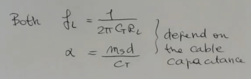
- The lower cutoff frequency: comes from the electric part here: , and you see that it depends on the total parallel resistance and the total capacitance.
⇒ Therefore, if the cable used to connect the device to the front end varies/changes, then also this frequency here will change.
NOTE: we have said before that the lower cutoff frequency was and i belive it to be more accurate.NOT_SURE_ABOUT_THIS
NOTE: probably the professor got confused with the charge amplifier lower frequency limit.NOT_SURE_ABOUT_THIS- And what is more severe, worst problem, is that also ==the sensitivity depends on this capacitance ==:
To solve the “dependecy from the cable” problem we can make the amplifier (read-out electronics) a part of the sensor itself, this particular kind of piezo-accelerometer are called IEPE or ICP:
- So in this case, is fixed. ⇒ Problem Solved.
Also look at charge output accelerometer
Memory Card
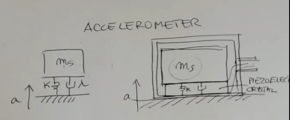
- The structure is the same, a simple sismic mass accelerometer with a spring dump system.
- However the spring is made up of quartz, let’s say it’s a piezoelectric layer.
- As usual this two surfaces (above and below the piezoelectric layer) are covered by a conductive layer, each surface is connected to a wire and this two wires are brought out of the case.
- Above all this there is a seismic mass case, which can be made of steel, for instance.
- Therefore, the mass of the crystal usually can be neglected, and the mass of this primary sensor coincides with the seismic mass.
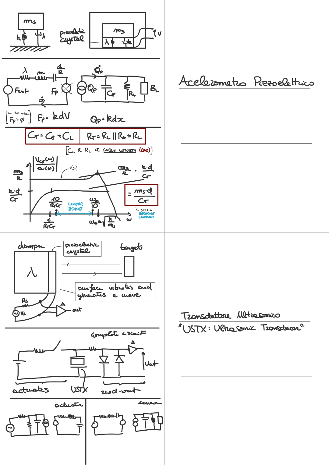
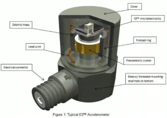
Here is the structure of a real life piezoelectric accelerometer.
Now, we can draw the equivalent circuit:
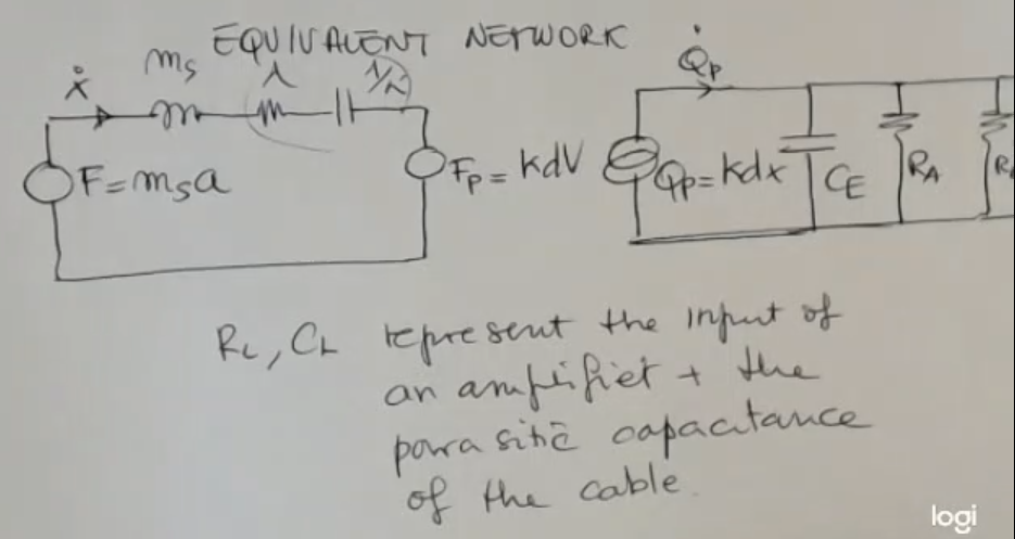
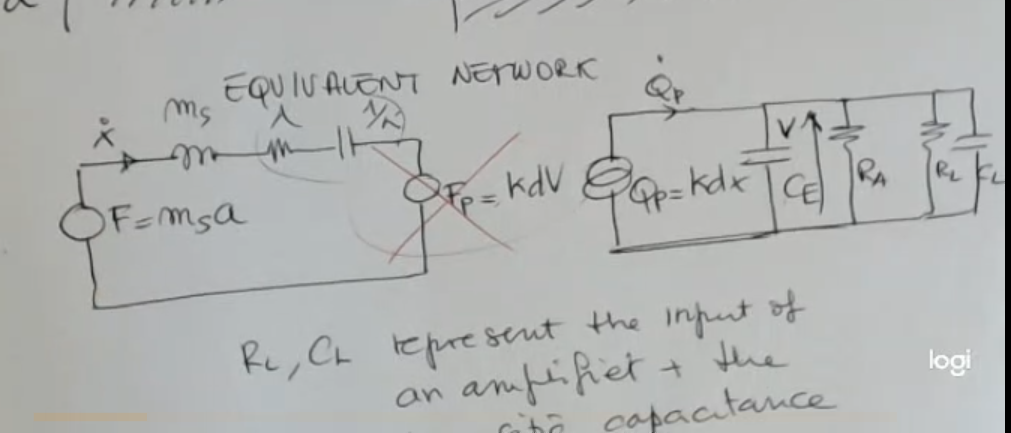
- For the mechanical part, is the same as usual.
- For the electronic part instead is similar to what we have seen before, for piezoelectric sensor, but in this case we have also and , this represent the input of an amplifier (, really large) and the parasitic capacity of the cable (, really small).
Also remember that is also very large. - Before going on, I remember that we can neglect , since this force is usually so small, very small with respect to (the external force).
So now we are, first of all, finding , as we have already seen many times:
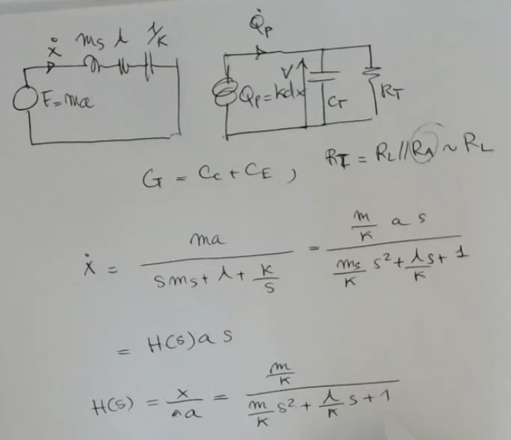
- is unused and did not exist previously, maybe it refers to , and the formula should be: NOT_SURE_ABOUT_THIS
Now we can write :
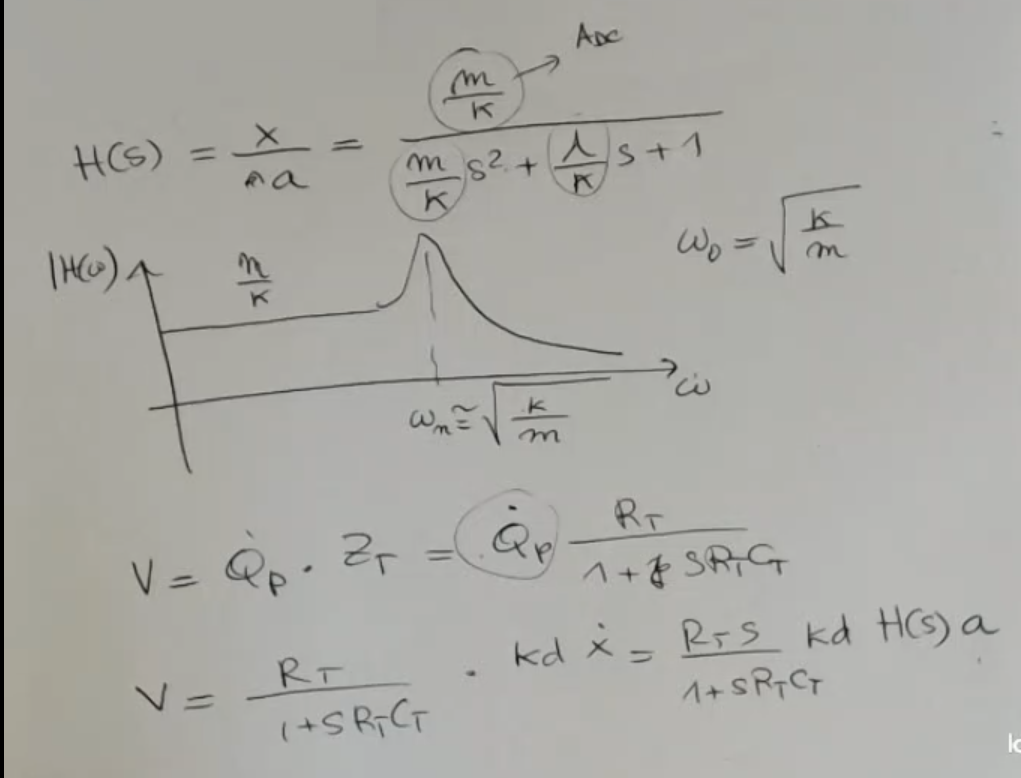
- : natural frequency or resonating frequency.
We can draw the input-output relationship module in the frequency domain:
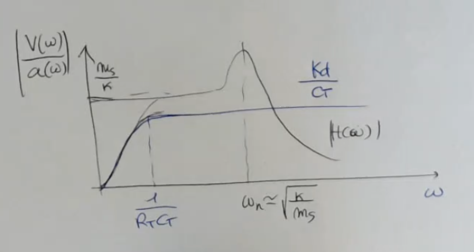
- In black the mechanical function we have seen before
- In blue the response of the electrical system, so the output voltage dived the acceleration, however we still need to multiply it by
NOTE: In the drawing the colors are invertedNOT_SURE_ABOUT_THIS - is a pole.
The overall function is:
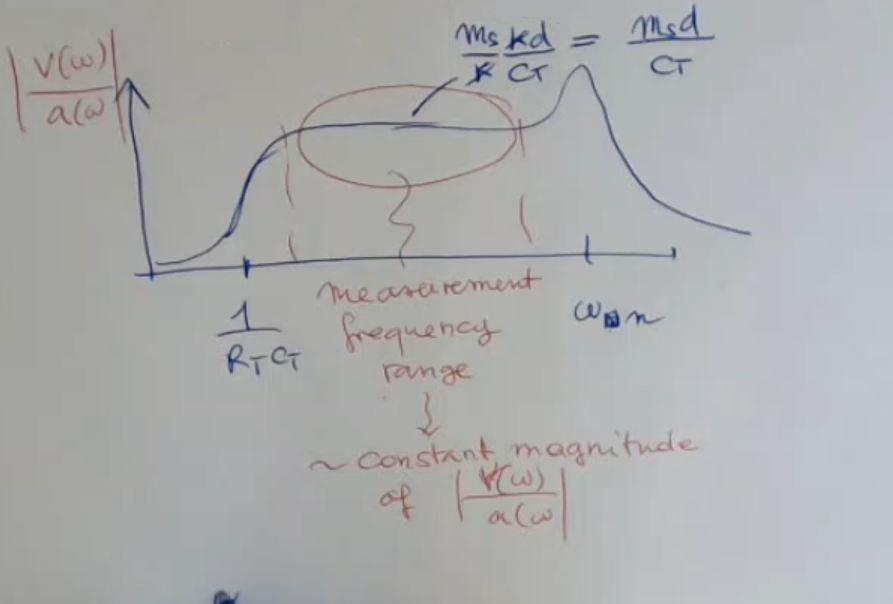
- So if we measure at the right frequency (inside the measurement frequency range) we will have a linear sensor, since the response has an approximately constant magnitude.
So we’ll also have a constant sensitivity.
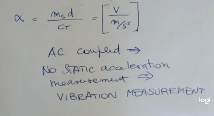
- We see that this kind of sensor and frontend, so the overall system is AC-coupled.
⇒ You cannot sense static acelerations. - So this device can be used only for dynamic acceleration measurements, that is for vibrations measurement.
- The low frequency cutoff comes from the electric part here , and you see that it depends on the total parallel resistance and the total capacitance.
⇒ Therefore, if the cable used to connect the device to the front end varies/changes, then also this frequency here will change. - And what is more severe, worst problem, is that also ==the sensitivity depends on this capacitance ==.
So:
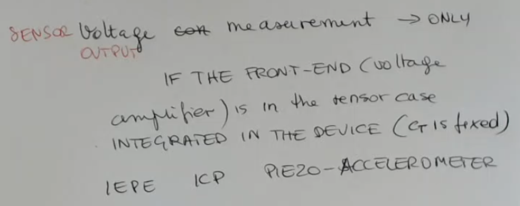
- So sensor voltage output measurement (which is crucial for readable outputs) can be performed only if the front end electronic, which is a voltage amplifier, is placed inside the case or connected with fixed wiring.
- And we speak about IEPE or ICP piezo-accelerometer, which are:
IEPE or ICP piezo-accelerometer
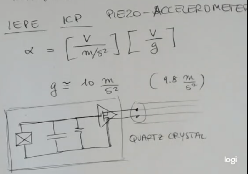
- The voltage amplifier becomes a part of the sensor itself.
- So in this case, is fixed. ⇒ Problem Solved.
- These two output wires are needed both for power in the amplifier and also for reading the output.
Since the output is an AC, you can exploit the same two wires, because the power supply needed by the amplifier is a DC value, whereas the output of the sensor is an AC value, so you can filter and use the same wires to give both - Sometimes you can use devices where the front end is integrated into the case of the sensor, and in this case the ouptut wires are directly connected to the crystal, so what we have as output is a charge.