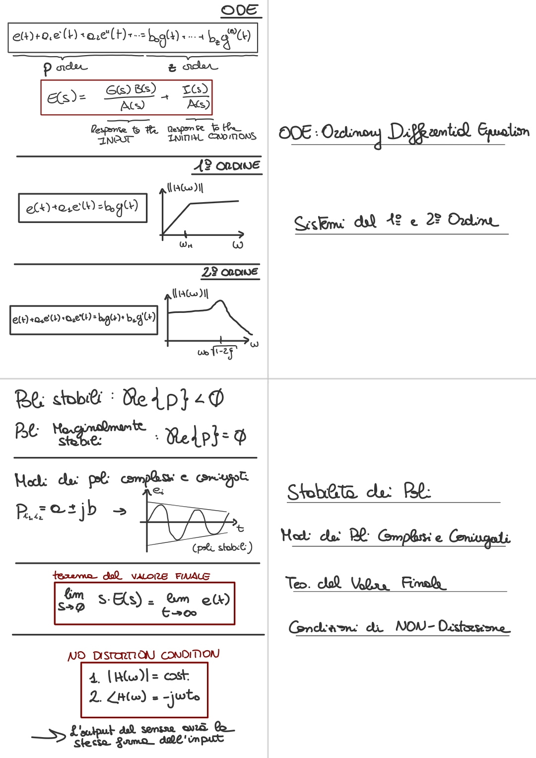
Remeber:
Now we will see the plot for a high-pass filter:
There is no response to static input to a continuous input. In fact is equal to . That means that lean means for which goes to then divided by is equal to:
- So for sure we don’t have any response to a continuous input.
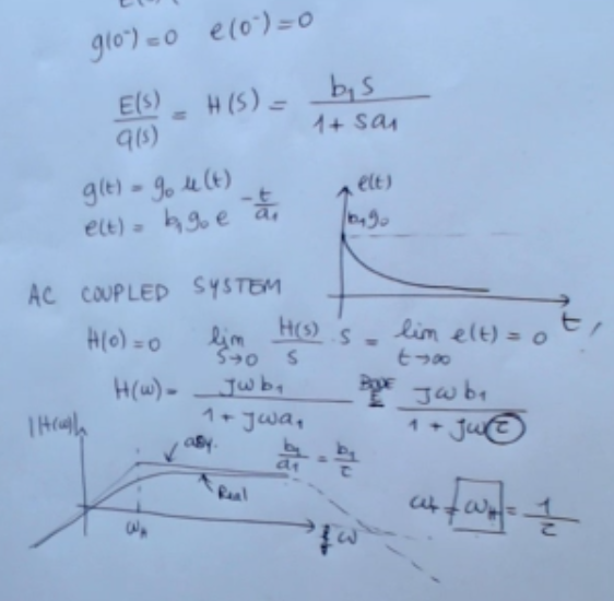
==AC Coupled System:
Only the alternating part (depending on ) passes trhough the system, there is no continuous input==.
For the real behavior, obviously we don’t have any real system which behaves as the system here, because at the end all systems have an output which goes to zero with infinte frequency (we draw the real behaviour as the dotted line), so this is an approximation of a real system which holds for some simple devices, like for instance, the most simple one I have mind is the high pass filter. So this is very simple high pass filter.
So obviously this is an approximation because at the end the parasitic capacitance will play a role and so we will have something different from this many other effects at the end for sure, we will not see again an infinite frequency which is a constant it will go to zero. So here we are simply neglecting the poles which have higher frequency and looking at the most relevant behavior of the system which is the one that can be described by this simple system (also this process or simplification is known as “dominant poles”).
Memory Card
Start:
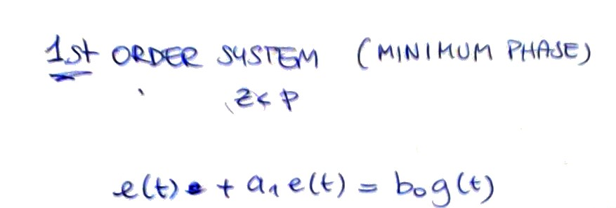
- ==NOTE: The first term should be .==
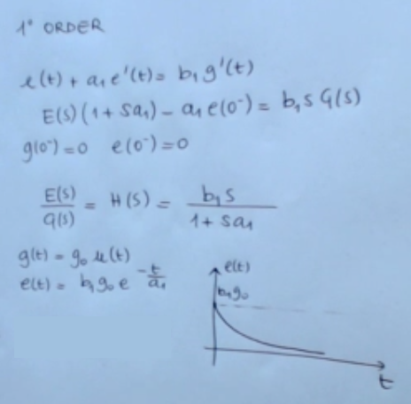
Laplace domain: 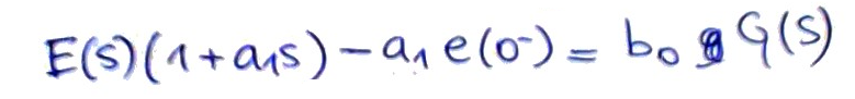
 If we consider the response to a step input:
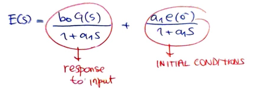
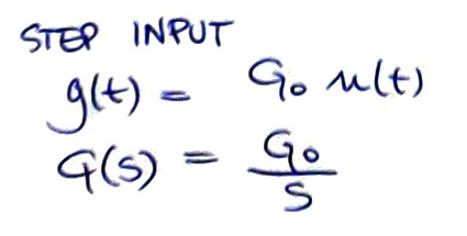 We can write this:
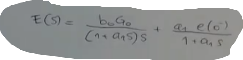 Here you have the respons to initial conditions:
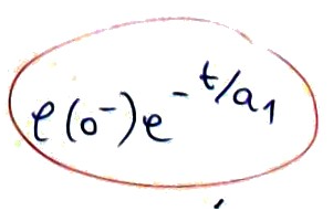 Here you have the response to the input:
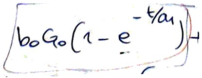
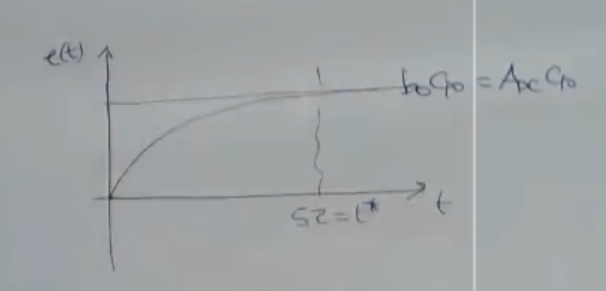
Response to the input:
Response to initial conditions:
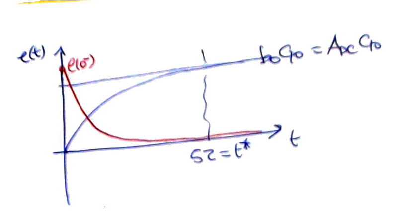
Super-imposition of the two:
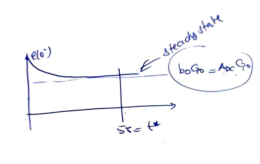 ==So from now, I know that when I suddenly change the input of the first order system,
I must wait for a time given by approximately five times the time constant of the system before reaching the steady state condition.
And also I know that the so-called DC gain is given exactly by the sensitivity of the system in static condition==.
==So from now, I know that when I suddenly change the input of the first order system,
I must wait for a time given by approximately five times the time constant of the system before reaching the steady state condition.
And also I know that the so-called DC gain is given exactly by the sensitivity of the system in static condition==.