Remeber:
We need to distinguish between:
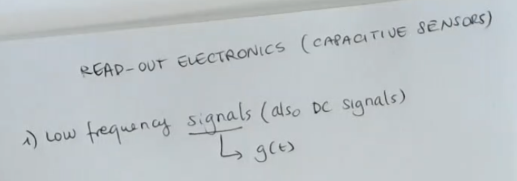
- Low frequency signals or DC signals.
So If the quantity we are measuring changes its values really slowly.- High frequency signals.
For low frequency signals, we will need an AC exitation to make the capacitive sensor work. Since the signal varies slowly, what happens is that the capacitance takes a value which is constant for a long time.
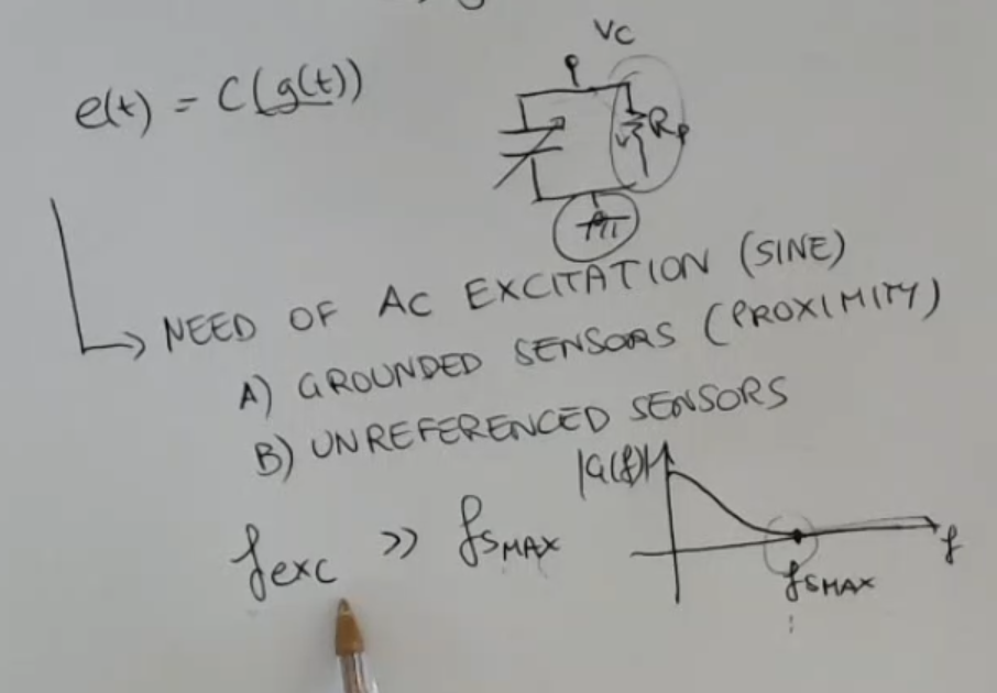
This time is enough to allow the loss of the charge which is stored in the capacitors due to the parasitic resistances.
==Remember that when thinking to a capacitance, we also have to imagine that there is always this parallel resistance: ==.
⇒ In this case we need to vary the charge by exciting the capacitance with AC excitations (so a variable excitation), so will be an AC exitation (for simplicity a sine wave).
==Also the frequency of the excitation () has to be selected, and it has to be much larger than the maximum signal frequency ()==.We have found two different readout solutions to the low frequency signal problem:
- FM: Frequency Modulation which uses a grounded sensor.
- AM: Amplitude Modulation which uses an unreferenced sensor.
So, we spoke about capacitive sensors and about the main problem of capacitive sensors:
- We underlined that there is the need of using shields.
- We also underlined the difference between grounded sensors and unreferenced capacitive sensors because they admit different solutions, for the read-out electronics.
So now we will say something more about the readout electronics for capacitive sensors.
We distinguish two different applications for these sensors, the first is related to low frequency signal and it is the first one that we will discuss.
First of all, we’ll speak about the case in which capacitive sensors are used to measure
low signals or static signals.
- So the quantity that it is sensed by the sensor is a slow varying signal, this signal here is referred as so the input of the sensor.
- We will have a sensor which transduces this quantity into the capacitance.
So our sensor will give us , where:- : output of our sensor
- : means that the output will be a capacitance depending on
- : input of the sensor
- So in any case this signal here varies slowly, and what happens is that the capacitance takes a value which is constant for a long time.
This time is enough to allow the loss of the charge which is stored in the capacitors due to the parasitic resistances.
==Remember that when thinking to a capacitance, we also have to imagine that there is always this parallel resistance: ==.
⇒ In this case we need to vary the charge by exciting the capacitance with AC excitations (so a variable excitation), so will be an AC exitation (for simplicity a sine wave).
Also the frequency of the excitation () has to be selected, and it has to be much larger than the maximum signal frequency (). - Remember that for capacitive sensors, we have to distinguish always between:
- Grounded sensor, (remember about proximity sensors).
So this kind of sensor which has the requirement of having one of the two terminals referenced. - And the other type are a referenced sensors.
In this case we are completely free to choose the best readout topology, because we have no constraints about the grounding of one of the two terminals.
- Grounded sensor, (remember about proximity sensors).
Under all these assumption we can find two types of readout electronics:
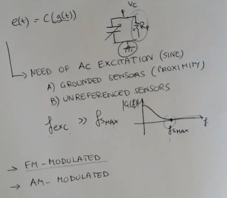
- FM modulated:
Circuits which are based on a strategy which considers the frequency modulation of the signal. - AM modulated:
Based on amplitude modulation.