Remeber:
- One of the most important advantages is that they usually give a very large signal as an output.
- They are also robust.
We define as we have done previously for the other lumped parameter systems an effort quantity (analog to the voltage in an electrical system), and a flow quantity (analog to a current), so for :
- Effort quantity: (Magneto Motive Force) (ampere turns, since it is found multipling the current per the number of turns of a inductance).
- Flow quantity: (Flux of the Magnetic Field) (volt seconds).
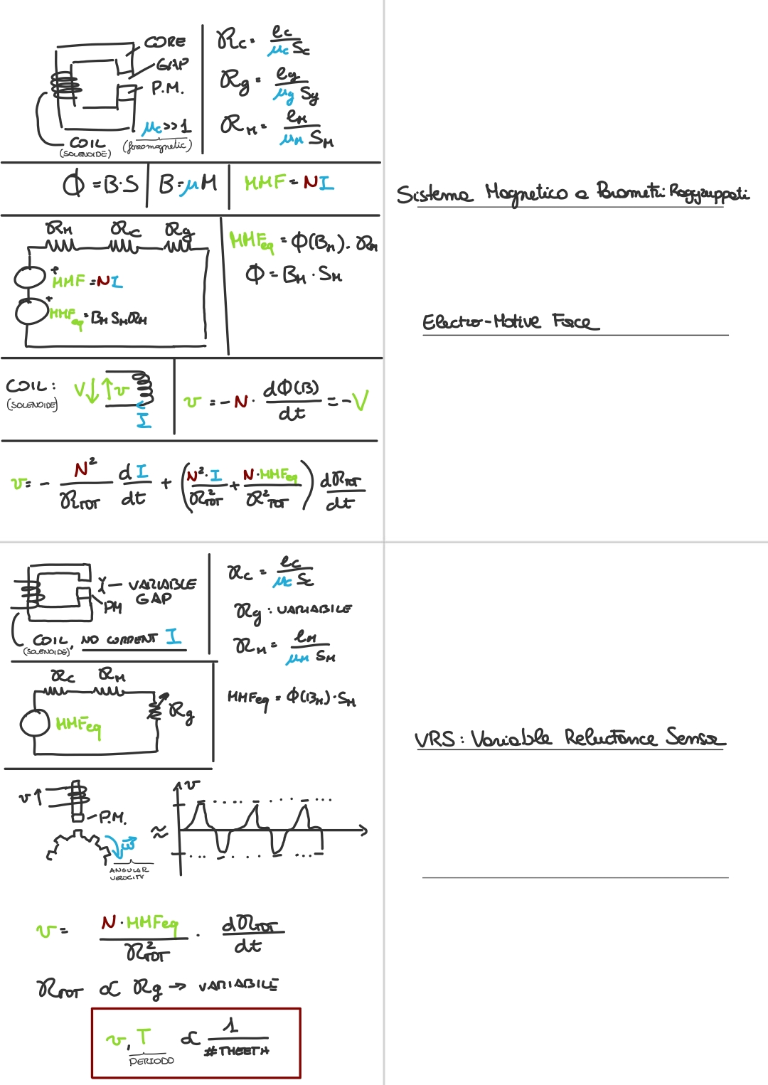
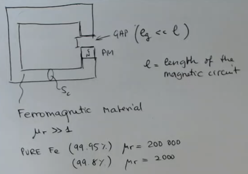
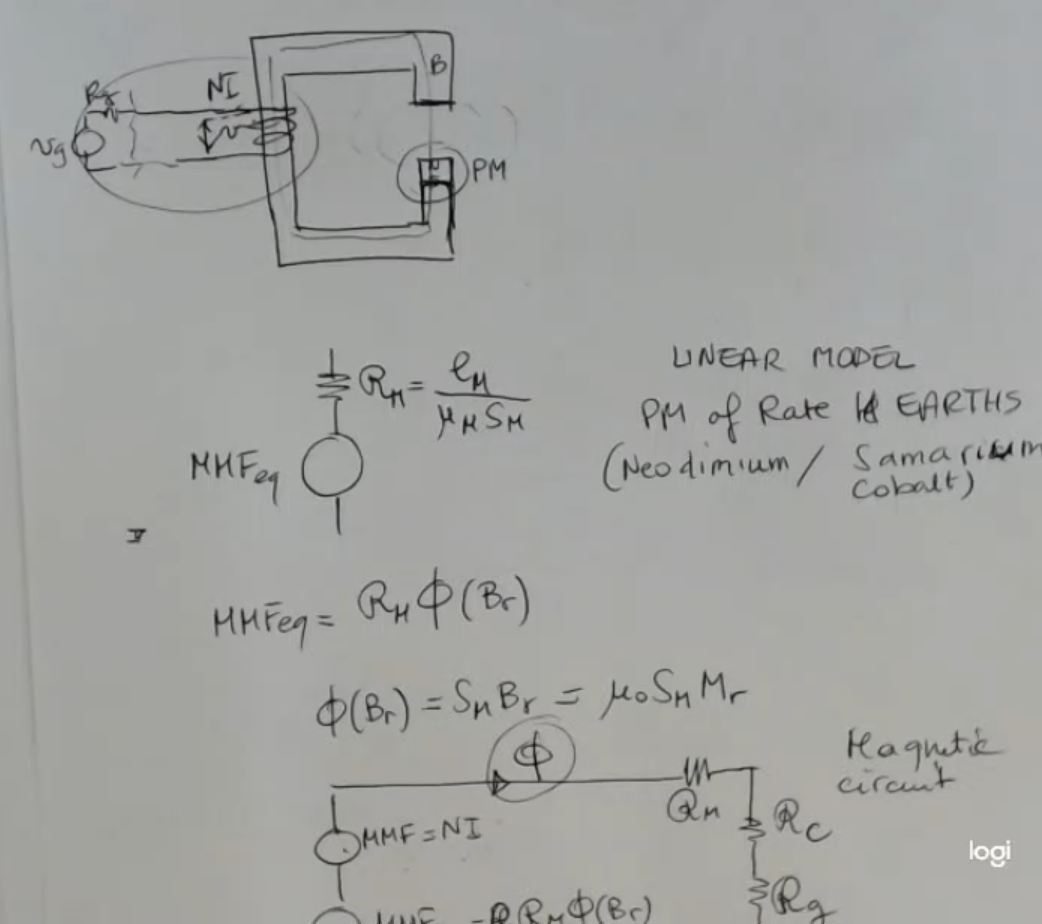
This is the basic structure of a magnetic circuit:
- : length of the gap.
- PM: permament magnet.
- A magnetic circuit is made of a material which is ferromagnetic, we call this whole lump of ferroelectric material “the core”.
For reference: An electrical circuit is a conductive circuit.- A ferromagnetic material is defined a such if it has a .
~ For example pure iron at has a , while if it is pure at it has a .IMPORTANTE
This way we can consider the filed to be enclosed in the core, and outside.
NOTE: This is similar to electrical circuit were the resisitivity of air and wire differ of around seven orders of magnitude, however for magnetic circuits the difference is not so big.- core surface (the pedix will always refer to the core).
- : length of the whole core, or magnetic circuit.
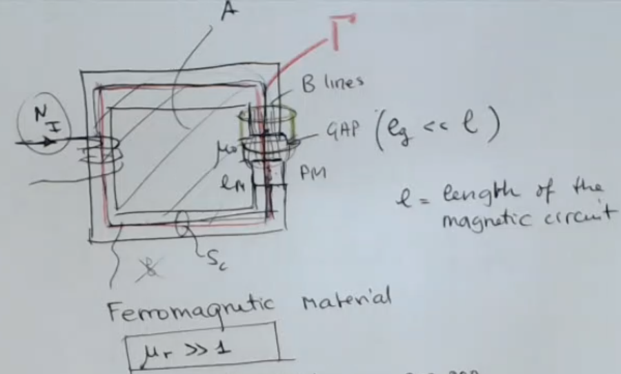
- Since there is a gap in the core of a magnetic circuit, we actually have a “broken core”.
- We can imagine a uniform field across the core and instead at the gap we have a distortion of the field, so the field tends to enlarge.
However if we consider (so small gaps) ⇒ then we can imagine that the field shape is the same, and it’s like similar to a current flowing trough:
Here is the lumped parameter circuit for a magnetic circuit without a permanent magnet:
Here are the formulas:Where:
- (permeability of the core).
- is the magnetic field intensity, also remember that .
Instead a permanent magnet, can be modelled as a voltage generator in series to a resistance, with values:
So: Where:
- .
- is the magnetization, we can calculate it as:
- is the magnetic susceptibility.
Then if we consider the complete magnetic circuit, including a PM (permament magnet):
- ==I call this the “electro-motive force” across the coil==.IMPORTANTE
This is actual voltage measured in Volts, but has sign inverted with rispect to the actual voltage drop.- We can see this voltage as the output of our system.
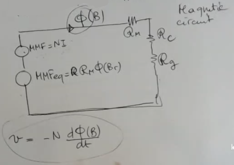
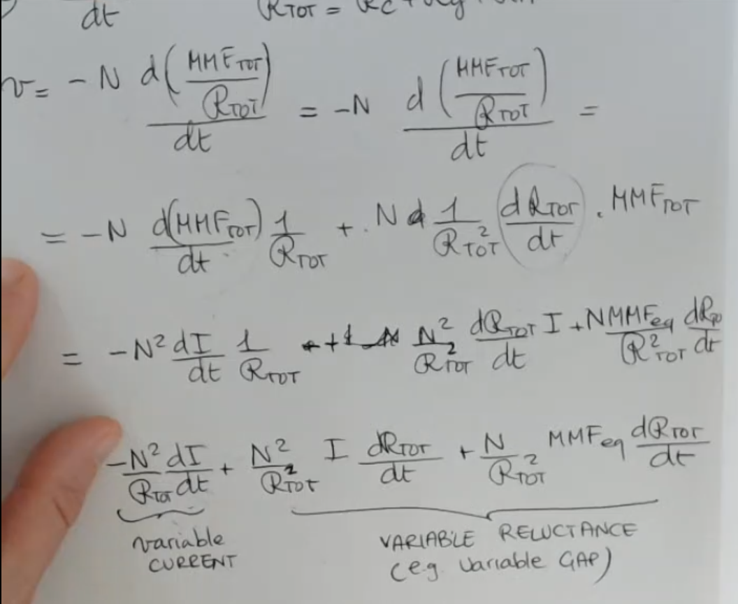
If we perform the calculation of the electro-motive force: We can split the results into this two contribution:
- Variable Current:
- Variable Reluctance:
- If one or both are variable in time I’ll have a change in the output voltage.
- How can the reluctance be variable?
⇒ For instance, if the length of the gap is variable, this can be an example of a displacement sensor).
Here are some example on how we can create magnetic sensors using the principle of variable current and variable reluctance:
Memory Card
Index
Introduction to the Magnetic Circuit
- One of the most important advantages is that they usually give a very large signal as an output.
- They are also robust.
So in order to have a summary of what happens in this field, it is useful to introduce the magnetic circuit:
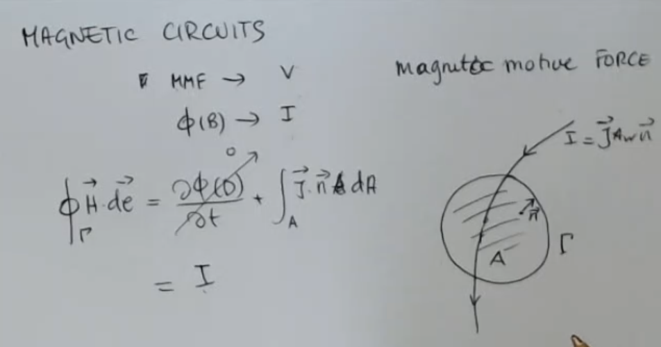
- So magnetic circuits are the analogous of electrical circuits, we will find a quantity which is magneto motive force (MMF).
Which is the quantity similar to voltage. - Flux of the field () instead, which will be the analogous of current.
- Whereas the electrical circuit model the reality very well, in this case instead for magnetic circuits, the model is far less accurate.
- The most important laws that we exploit to form this kind of circuit:
- We take a curve , which supports a surface with a normal (vector perpendicolar to the vector) in each point, which I call .
Then we consider current flowing through this surface , the current is equal to:Where: is the current density vector. - If I take the line integral over of the magnetic field (), than we have that it is also eqal to .
(Considering to have a static or no electrical field, so that )
- We take a curve , which supports a surface with a normal (vector perpendicolar to the vector) in each point, which I call .
- NOTE: In this example the surface is generic, it can be both defined as closed or open.
NOTE: Closed Surface: means a surface that encloses a volume. Open Surface: means a surface that does not enclose a volume.
And then again, if I instead consider the integral of the electrical field on the line :
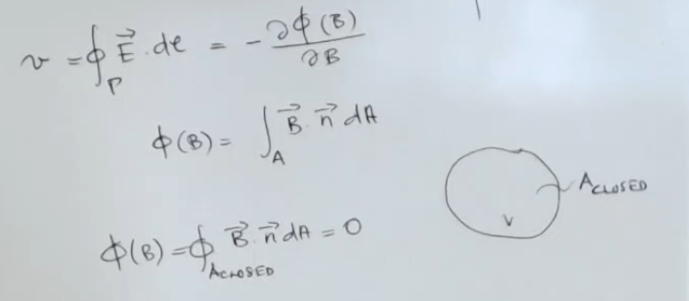
- : is the voltage that I can measure along this line .
- Remember that the flux is the flux of the field over the surface (: generic surface can be both closed or open).
- Finally remember that if I take a closed surface , so that encloses a volume. we have that: the flux .
Magnetic Circuit
Now let’s take the structure of a magnetic circuit:
- : length of the gap.
- A magnetic circuit is made of a material which is ferromagnetic.
- An electrical circuit is a conductive circuit, instead here we have a ferromagnetic circuit, so we consider a structure like this:
- We take a core (the whole ferromagnetic material)
- I place also a permanent magnet (PM)
- And then I add a gap.
- So you have to imagine that this “C shape” is made of iron and closed with this permanent magnet here.
- I consider this to have a surface ( : Core), which is uniform all along the circuit, for simplicity.
- And I consider this gap to have a length , which is much shorter than the overall length of the circuit ().
Why this is a magnetic circuit?
⇒ Because I consider this to be a ferromagnetic material.
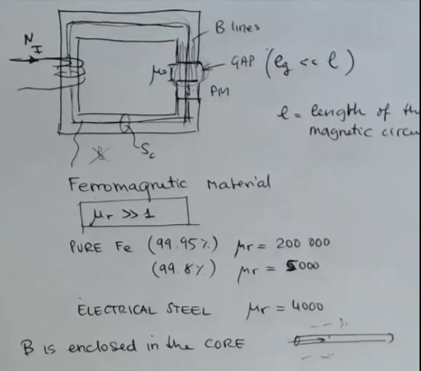
- Ferromagnetic material, are materials which have a magnetic permeability (), which is much larger than .
- What does it matter?
⇒ It means that we can consider, that if I put here a coil made up of turns, that wraps around the core, and I let a current flow through it, due to this permanent magnet, the field is enclosed in the core.
⇒ So it’s like having a so different value of the B here outside the core and inside the core, that is like having outside. - NOTE: That this is similar to electrical circuit were the resisitivity of air and wire are around seven orders of magnitude, in case of magnetic circuits you don’t have this exactly this situation, but with a certain approximation, we can think that the field is all here and follows the geometry of the core.
- What happens at the gap?
⇒ We have a “broken core”.
We can imagine a uniform field across the radio direction instead here we have a distortion of the field, so the field tends to enlarge.
For small gaps, we can imagine that the field shape is the same, and it’s like similar to a current flowing trough, instead this time is the field which is enclosed here.
So now we can take a line which follows the shape of the circuit, and we can write the following:
The first assumption, no permanent magnets:
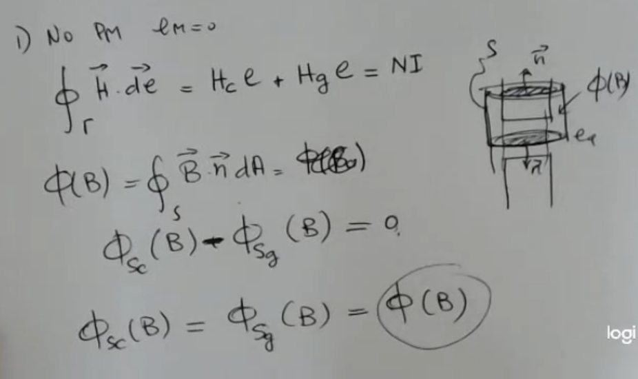
- (permaennt magnet length) equal to .
- So in this case I can write selecting a curve which follows the shape of the core and I can evaluate the integral of the line integral over .
- I suppose to have uniform value of the field over the line in the core and in the gap.
So different but uniform and all the field lines are parallel to gamma (so ) - Now we can go on, and take a closed surface which has a cylinder shape like this (, shape defined by and both taken arbitrarly big to encapsulate the core), then I evaluate the flux of the field .
- We have:
- (core)
- (gap)
- (flux of the magnetic field over the core surface )
- (flux of the magnetic field over the gape surface )
- This means that the flux is the same in the gap and in the core.
Now I can relate the flux with the value of the field inside, and we know that for instance the flux in the core of the field will be:
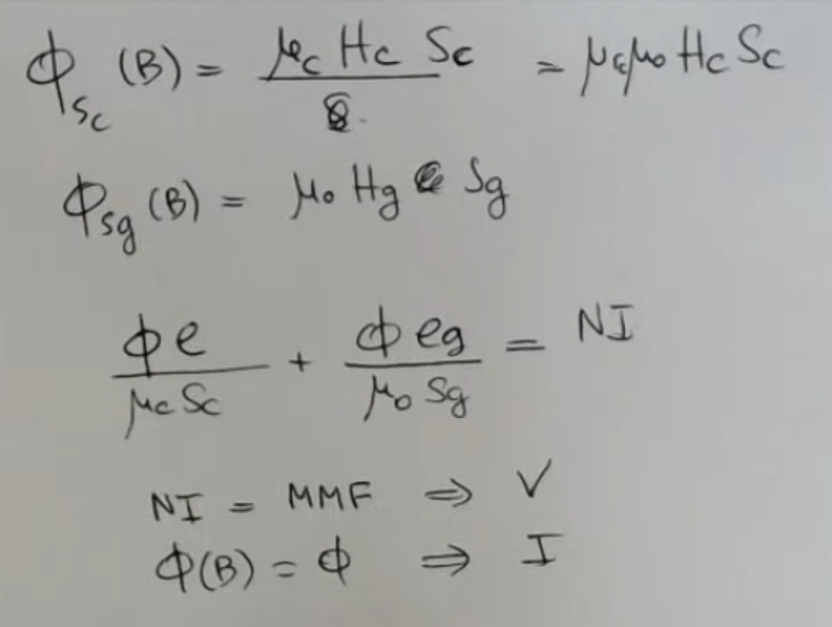
- I consider everything uniform, for simplicity.
- Since we have said I will just call it for readability.
- NI is called the magneto motive force and is treated like a voltage,
- the flux of is treated like a current.
So here is the magnetic circuit:
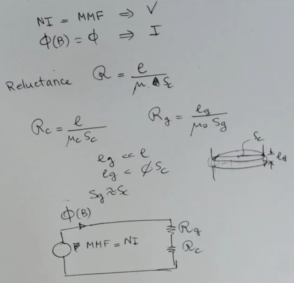
- : diameter of the surface
- I have two different components for my magnetic circuit since I have diregraded this permanent magnet, so I have to define two reluctances:
- Reluctance of the core ()
- And then the reluctance of the gap ()
- And instead of resistances, we have reluctances gap and reluctances core.
So now we are ready to place back our permanent magnet into our circuit:
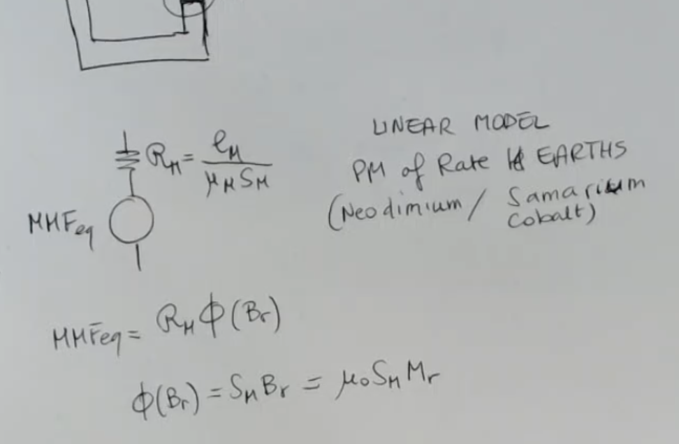
- PM : Permanent Magnet
- : flow generated by the magnet itself, which is due to the residual magnetic field (the magnetization of the magnet).
- : is the magnetization of the magnet.
- (index) : thing realted to the magnet.
- I did this very large gap, but you have to think that this should be a small distance.
- The permanent magnet will have both a relucatnce (it is a piece of ferromagnetic material), but it will also have its own magneto motive force (“voltage”) generator.
The permanent magnet can be inserted in the circuit, replacing its equivalent, which is for sure a reluctance:
- So we have a complete model of this circuit where I placed both a coil and a magnet as sources for the field.
So I write it again:
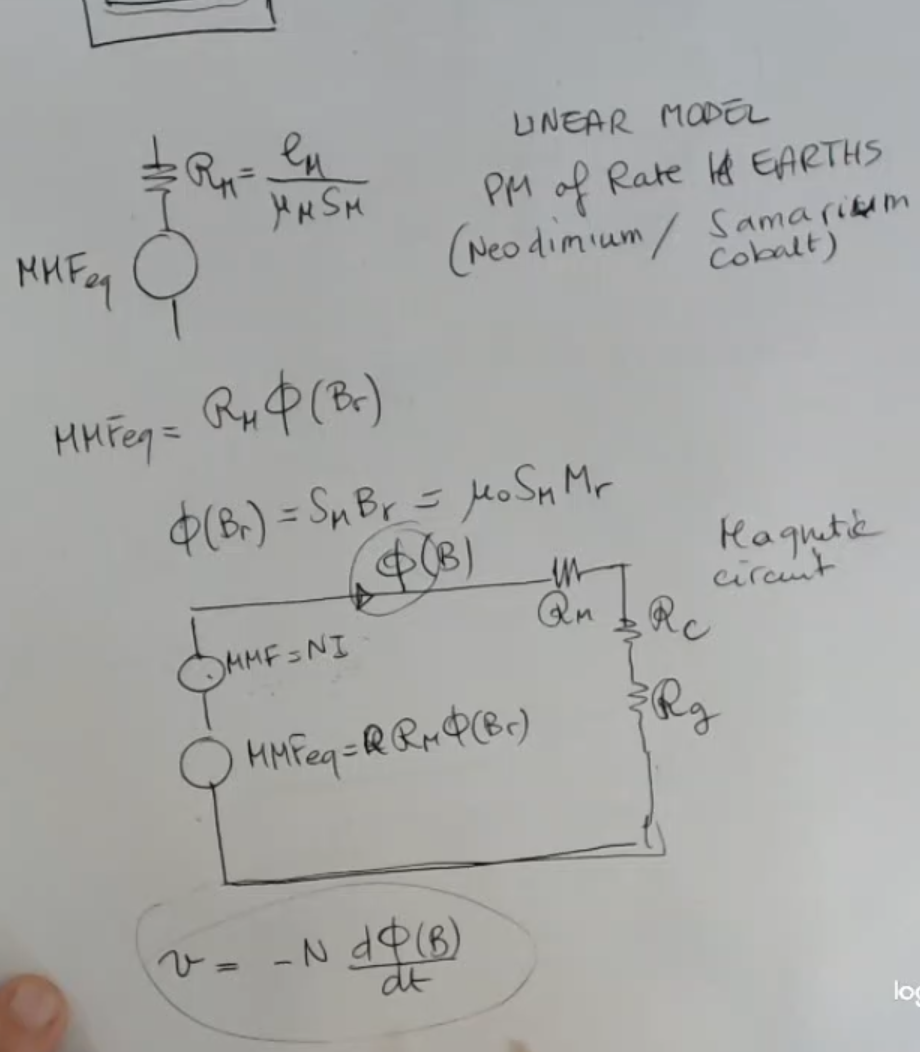
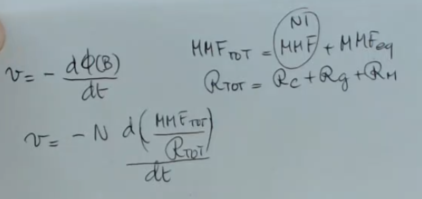
- I call this the electro-motive force across the coil (this is actual voltage measured in Volts, but has sign inverted with rispect to the actual voltage drop).
- Where:
- MMF derived by
- MMF derived by the permanent magnet.
- We can put something as an external circuit, something here it could be a generator and a resistance or other pieces of electrical circuit.
- So now we can also describe the effect of the magnetic behavior on the electrical circuit because ==we know that for induction these are coupled==.
More calculations:
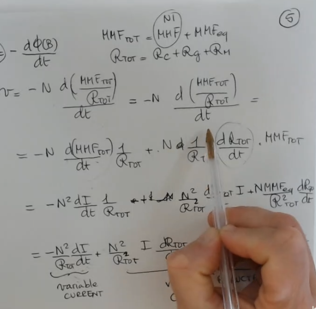
- So at the end we can split the electro-motive force total into this two contribution:
- Variable Current:
- Variable Reluctance:
- If one or both are variable in time I can read the output as a voltage.
- How can the reluctance be variable?
⇒ For instance, if the length of the gap is variable, this can be an example of a displacement sensor).