Remeber:
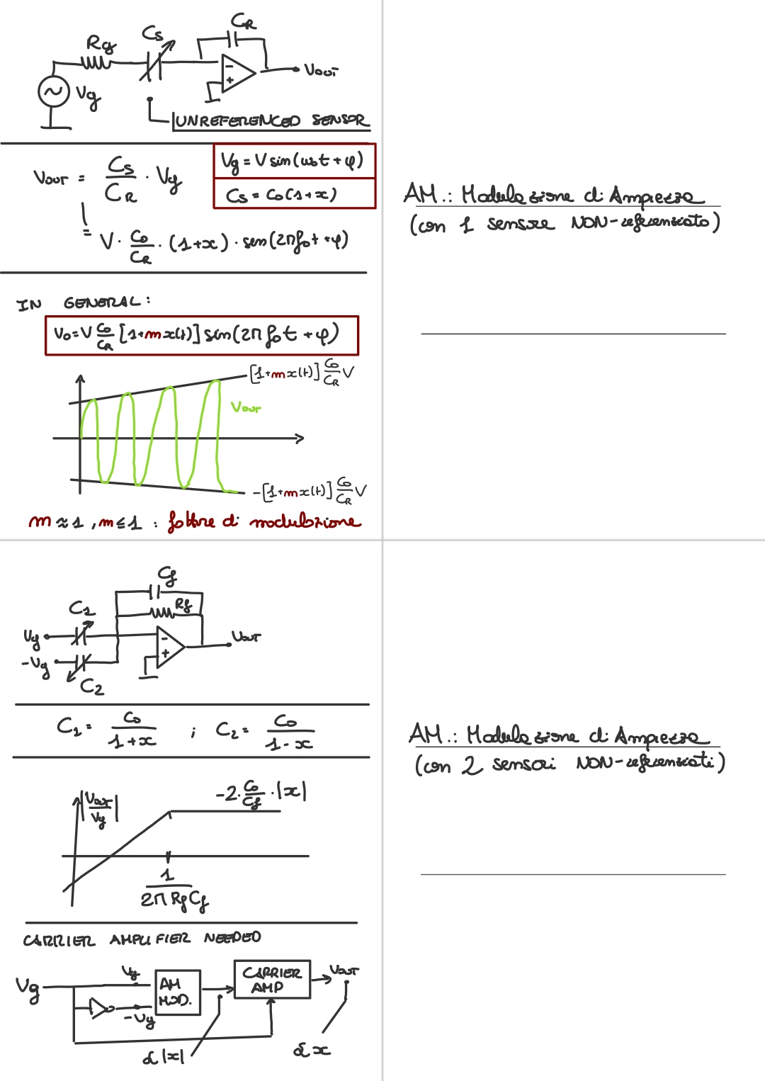
The simplest circuit for Amplitude Modulation:
The output will be:Where:
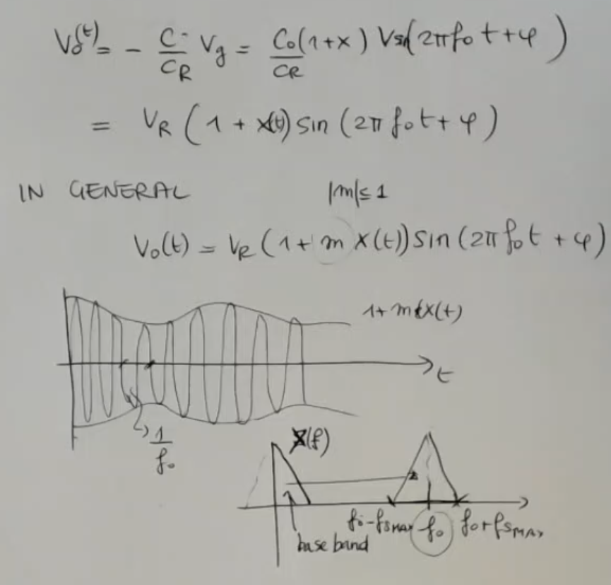
We have defined the general formula of the AM modulation as:Where:
- is a modulation factor and we have that (usally less than ).
From the spectrum we understand that if this frequency is much larger than the value of the maximum frequency of the signal , then the recover of the signal is easier:
Instead, if the shifted frequency were more close to the original frequency (the base band) of the signal, then there will be difficulties in the demodulation process.
We have also seen the complete circuit for amplitude modulation.IMPORTANTE
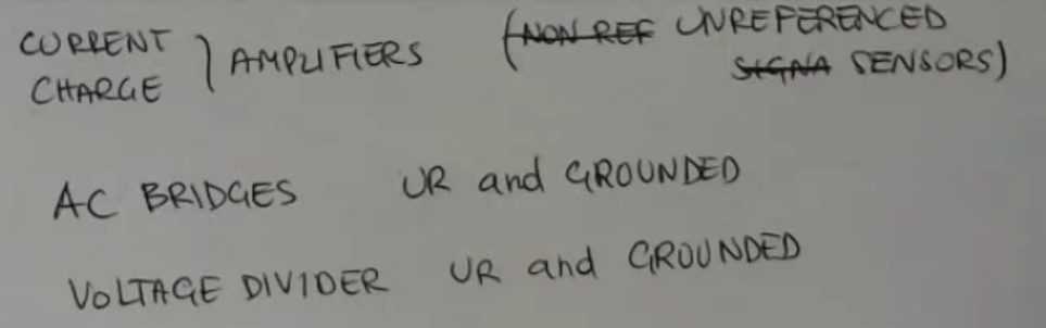
We can list a certain amount of circuits, which are good for this application:
- Current or charge amplifiers.
And this obviously can be used with unreferenced signals and sensors.- AC bridges.
Like we have seen the resistance bridges, we can form bridges with capacitance and resistances.
This is good for both referenced sensors and grounded ones.- Voltage dividers:
Which can be used with unreferenced and grounded ones.
Memory Card
AM: Amplitude Modulation
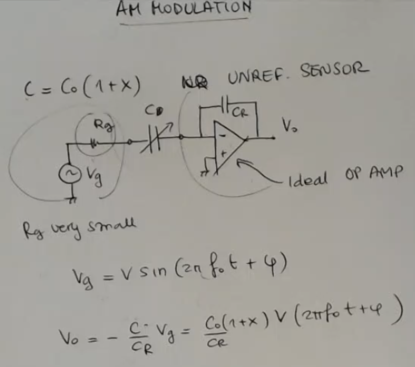
- This time we define , and it has to be an unreferenced sensor.
- : reference capacitance.
- and : AC source and resistance.
is considered to be very small so I will neglect it from now on.
In practice this means that we have to take a good voltage generator. - And we have seen that this is a good solution because, in terms of sensitivity to electrical noise.
- is the excitation frequency, so I select it arbitrarily.
- The output function is a little wrong:
- So in general, using solutions like this in which our capacitance is a part of the gain of the circuit (of the amplifier) with a topology selected in the particular case to be suitable for this situation.
- is usually less than 1, like before (in the FM we called it to enfasize that in FM we talk about frequency, in AM about amplitude, they should both represent the sensitivity of the capacitive sensorNOT_SURE_ABOUT_THIS ).
- Here the bandwidth is easily found, so the description of the signal in the frequency domain is easily found.
- If this was the spectrum of the signal base band, the original spectrum, then the modulated signal is this one, and it’s frequency shifted, obviously by the modulation process.
From the spectrum we understand that if this frequency is much larger than the value of the maximum frequency of the signal , then the recover of the signal is easier.
Instead, if this is more close to the frequency of the signal, then there will be difficulties in the demodulation process.
And so we can list a certain amount of circuits, which are good for this application:
- Current or Charge Amplifier.
And this obviously can be used with unreferenced signals and sensors. - AC Bridges.
Like we have seen the resistance bridges, we can form bridges with capacitance and resistances.
This is good for both referenced sensors and grounded ones. - Voltage Divider:
Which can be used with unreferenced and grounded ones.
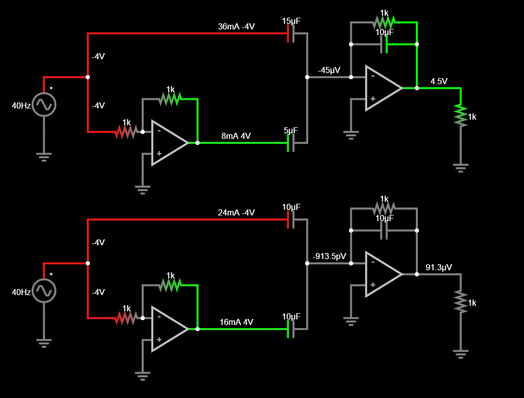
So for the complete AM circuit, I’ll do two examples, one for differential capacitance sensors:
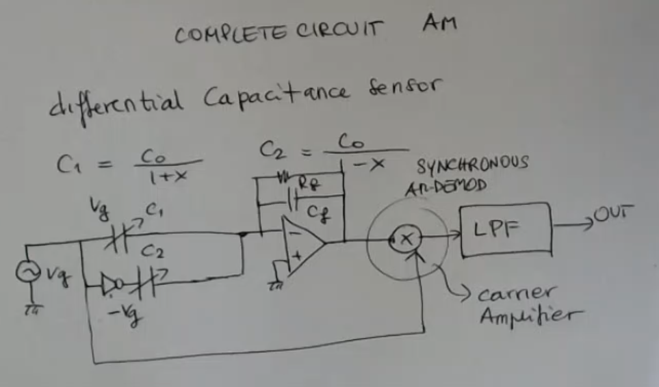
- Note: this is an inverting amplifier.
- So differential because the capacitances are:
- : needed to reduce the effects of DC errors of the amplifier.
- And then we can perform a synchronous AM demodulation (for instance, a charge amplifier), then low pass filter, and finally the output.
Circuit :