Remeber:
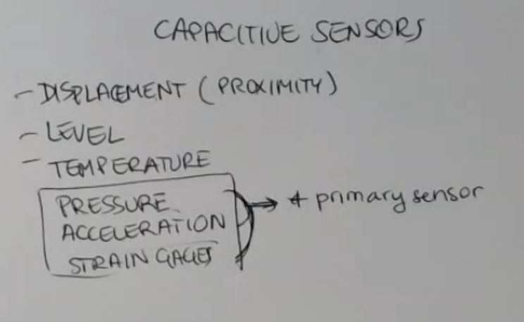
We will see different capacitive sensor:
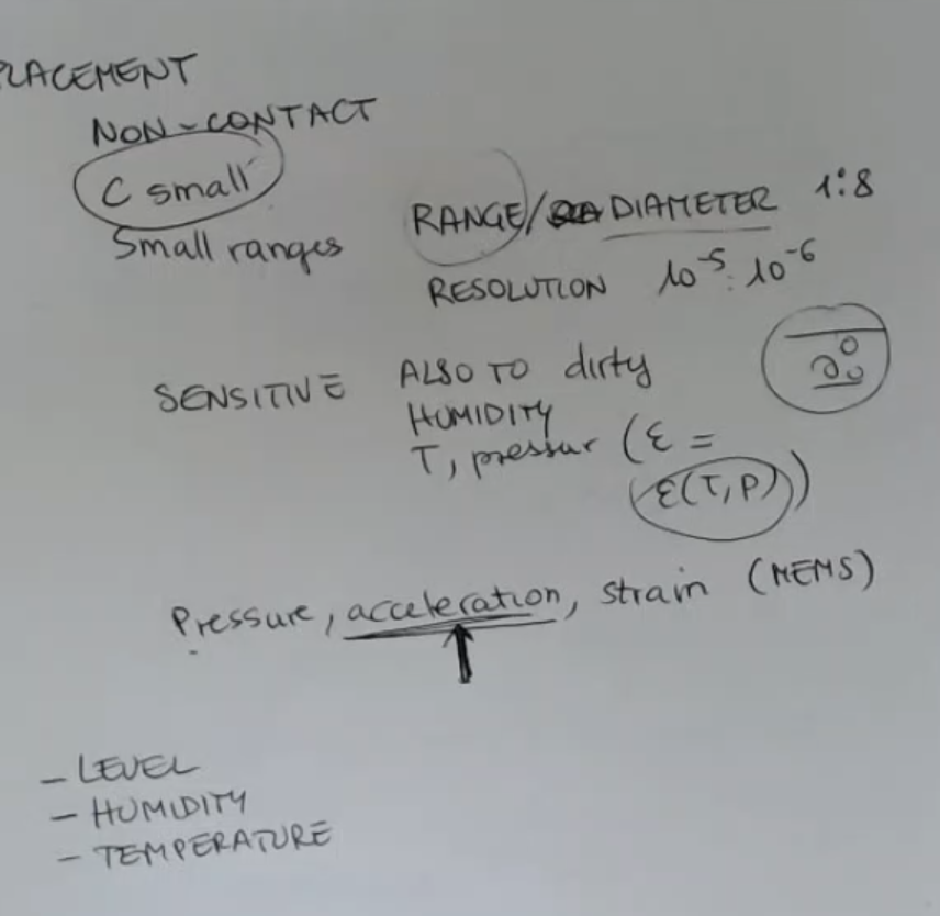
- displacement or proximity sensors.
- level sensors.
- temperature sensors.
And as primary sensors:
Advantages of Capacitive Sensors:
- They are non-contact
- Resolution, it’s very good for small ranges, we arrive to resolutions of this type: .
So we can sense very small variation of the distance.- Very simple structure, the sensor is just a metallic plate, it doesn’t matter which kind of metal, usually, and it doesn’t matter the shape, two metallic plate are enough to build a capacitance.
Disadvantages of Capacitive Sensors:
- The value of the capacitance are small.
- They can work only for small ranges, for small distances, this is one of the reasons because they are called proximity sensors.
We can write this simple relationship in order understand:
==The ratio: range (maximum distance that can be measured), to diameter of the probe (thinking about a circular probe, a circular plate), is roughly: ==.IMPORTANTE- Capacitive Proximity sensors are sensitive to dirt.
Dirt particles placed in between the two plates changes the permittivity of the medium, so it can affect the measurement.- They are also sensitive to humidity, but not so much, unless the water is condensed.
- And also to temperature and pressure, because the gas can change the permittivity as a function of temperature and pressure.
But this is for extreme condition, not for environmental condition.
So ==this is important only for industrial application, otherwise it’s not so severe of a problem==.
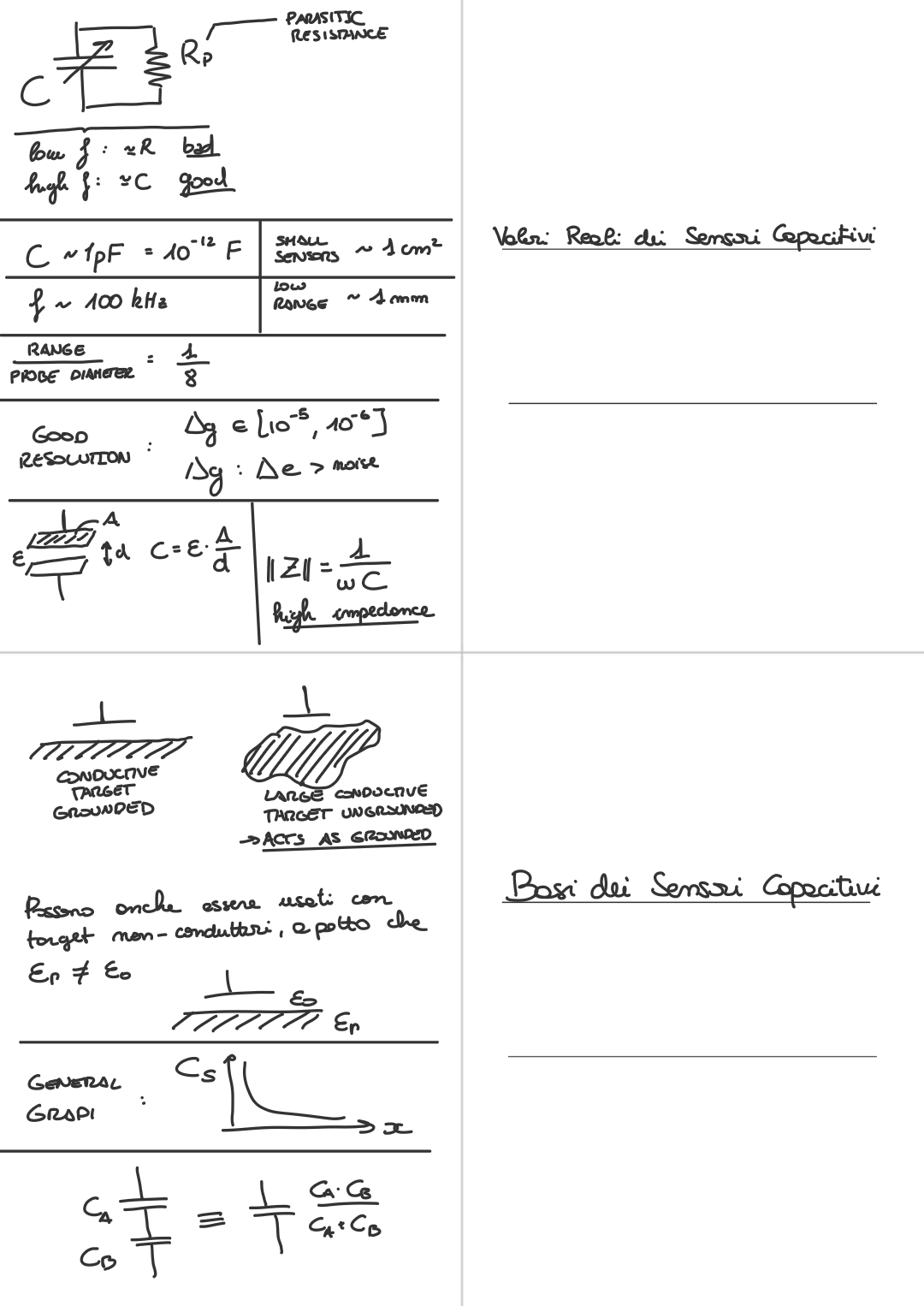
We always have to take into account that there is a parasitic resistance in parallel to a capacitance, the ideal capacitance does not exist, so let’s take as example a simple circuit:
- is my sensor (terminals and are not directly connected to ground).
- is the parasitic resistance.
- and are parasitic capacitances coupling my sensor to ground.
- ==Remember that these parasitic capacitances can change their capacitance value if the relative position of this object changes==.
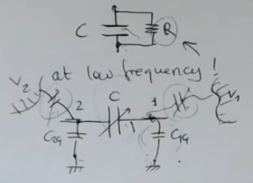
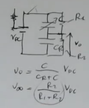
Here we can see another example where we consider the sensor , its parasitic resistance , the reference capacitance and its parasitic resistance :
- Since the values of the parasitic capacitance are really small, I find a voltage which depends only on the parasitic effect (at infinity):While at the start, it does not depend on or :==So remember that the prasitic effect for capacitive sensors is present at low frequency or for long time measurement==.
Let’s take some real world values as an example:IMPORTANTE
- Capacitice sensor measure a value of: .
We measure with a frequency of .
⇒ The resulting impedance is equal to , which is realy large.- Also remember that this sensor are small .
- And are used really close to the target (talking about proximity sensors) .
- This high impedance corresponds to a high impedance source.
⇒ ==It will be a problem if the front end electronic it’s not well designed, it will load the source==.
⇒ ==Moreover, with high impedance sources, you will have electrical noise, which becomes a large problem as we have started to see==.
Memory Card
Index
- Capacitive Sensors List
- Advantages and Disadvantages of Capacitive Sensors
- Parasitic Resistance in Capacitive Sensors
- High Impedance Source/Circuit in Capacitive Sensors
Capacitive Sensors List
Advantages and Disadvantages of Capacitive Sensors
-
They are non-contact.
-
But the value of the capacitance are small.
-
They can work only for small ranges, for small distances, this is one of the reasons because they are called proximity sensors.
We can write this simple relationship in order understand:
==The ratio: range (maximum distance that can be measured), to diameter of the probe (thinking about a circular probe, a circular plate), is roughly: ==. -
Resolution, it’s very good for small ranges, we arrive to resolutions of this type:
So we can sense very small variation of the distance. -
Capacitive Proximity sensors are sensitive to dirt.
Dirt particles placed in between the two plates changes the permittivity of the medium, so it can affect the measurement. -
They are also sensitive to humidity, but not so much, unless the water is condensed.
-
also to temperature and pressure, because the gas can change the permittivity as a function of temperature and pressure.
But this is for extreme condition, not for environmental condition.
So ==this is important only for industrial application, otherwise it’s not so severe of a problem==. -
Very simple structure, the sensor is just a metallic plate, it doesn’t matter which kind of metal, usually, and it doesn’t matter the shape, two metallic plate are enough to build a capacitance.
-
Remember that capacitive accelerometer are common for MEMS devices.
-
And then we have spoken also about some other types of sensor, that doesn’t share the problem of small capacitance, because there are devices which can be built to have a larger value of the capacitors.
And these are:- level (very common application)
- humidity
- temperature not (common).
Parasitic Resistance in Capacitive Sensors
We always have to take into account that there is a parasitic resistance in parallel to a capacitance, the ideal capacitance does not exist, so let’s take as example a simple circuit:
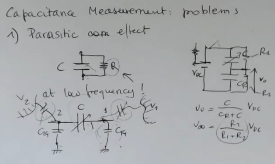
- Where:
- is my sensor (terminals and are not directly connected to ground).
- and are parasitic capacitances coupling my sensor to ground.
- With any other voltage source or charge, so for instance, a body, me, with triple electric charge over my body (in this example we call it ).
So I have also this capacitances surrounding my sensor, coupled by a means of electrostatic electrical field.
And this is represented by parasitic capacitance.
==Also these parasitic capacitances can change their capacitance value if the relative position of this object changes==. - Obviously, these parasitic capacitances can be small, because distance between the ground could be high, and maybe and the surface considered are small.
- ==At the end, I will find a voltage which depends only on the parasitic effect (at infinity), so remember that this is important at low frequency or for long time measurement==.
High Impedance Source/Circuit in Capacitive Sensors
Also related to this problem is the high impedance source/circuit.
For instance, if I take a small capacitance (a proximity sensor).
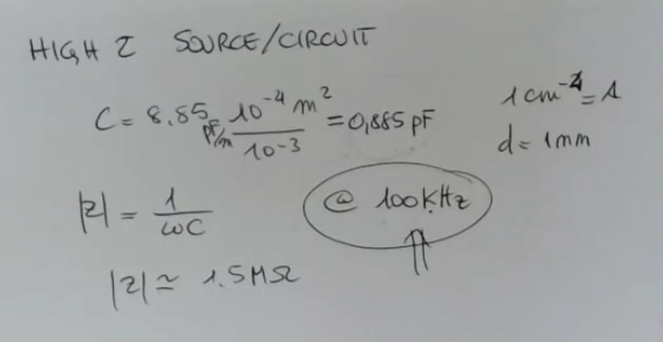
- So our capacitance is less than .
- If I calculate the magnitude of the impedance, at a frequency which is not so large, let’s say , I find an impedance of .
This means that if I use a smaller frequency, I will still have a very, very large impedance.
Obviously, this high impedance corresponds to a high impedance source. ⇒ ==It will be a problem if the front end electronic it’s not well designed, it will load the source. ⇒ Moreover, with high impedance sources, you will have electrical noise, which becomes a large problem as we have started to see==.
“It will load the source” means: “the components or circuitry on the frontend of a system draw electrical current or power from the source they are connected to”; if the load has not a big enough impedence the current will flow into it, not what we wanted
If I imagine a front end circuit, a simple voltage divider, with an AC source, like so:
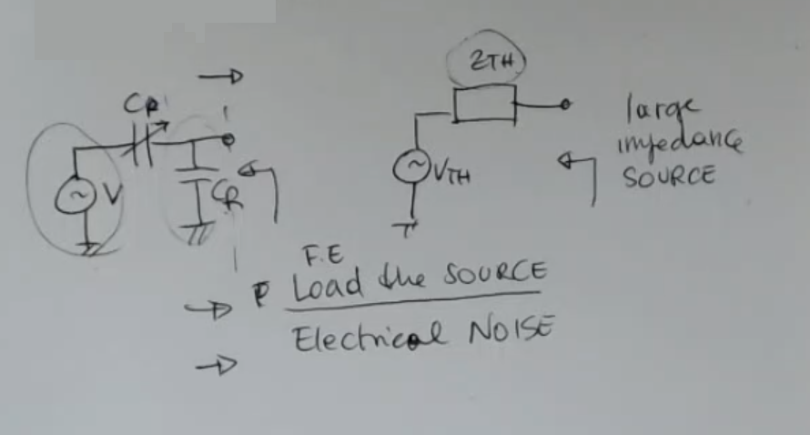
-
is the excitation voltage:
-
: is the reference capacitance, which can be used to read the capacitance of this sensor ().
-
So we do a Thevenin Equivalent:
- : the parallel of and , this impedance will be large, so I have a large impedance source.
And this is a problem because the frontend that comes after, can load the source.
If it’s not a good voltage source, I have to take this into account, and let’s say the front end can load the source.
And moreover, I have the problem of electrical noise.
- : the parallel of and , this impedance will be large, so I have a large impedance source.
-
What do we mean when we say that “A Frontend Electronic Loads the Source”?
- The phrase “A Frontend Electronic Loads the Source” typically refers to a situation in electronics and electrical engineering where the components or circuitry on the frontend of a system draw electrical current or power from the source they are connected to. In this context, let me explain the components involved:
- Frontend: The frontend in this context typically refers to the input or initial stage of an electronic system, often including sensors, signal conditioning circuitry, or any components that interact with the external environment or source.
- Electronic Load: An electronic load is a device or component used to simulate the behavior of a load (e.g., a resistor or a device being powered) in an electronic circuit. It allows you to test and characterize power sources, such as batteries or power supplies, by drawing a controlled amount of current from them.
- Source: The source refers to the power source or energy supply that provides electrical energy to the system. It could be a battery, a power supply unit, a generator, or any other source of electrical power
- When we say that “A Frontend Electronic Loads the Source,” it means that the components or devices at the frontend of the electronic system are actively drawing electrical current or power from the source. This action could be intentional, as in the case of testing and characterization, or it could be a normal operation of the system.
- In some contexts, it’s important to manage how much current or power the frontend draws from the source to ensure proper functioning and prevent overloading or damaging the source. This concept is essential in the design and analysis of electronic systems to ensure they operate correctly and efficiently.
- The phrase “A Frontend Electronic Loads the Source” typically refers to a situation in electronics and electrical engineering where the components or circuitry on the frontend of a system draw electrical current or power from the source they are connected to. In this context, let me explain the components involved: