Remeber:
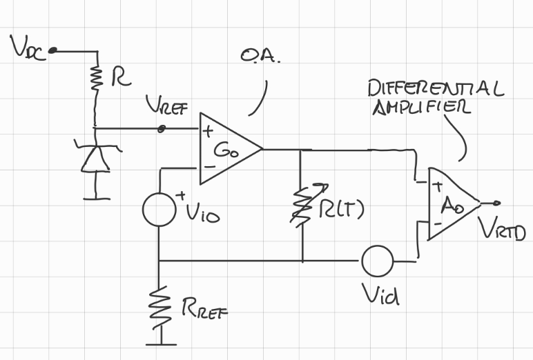
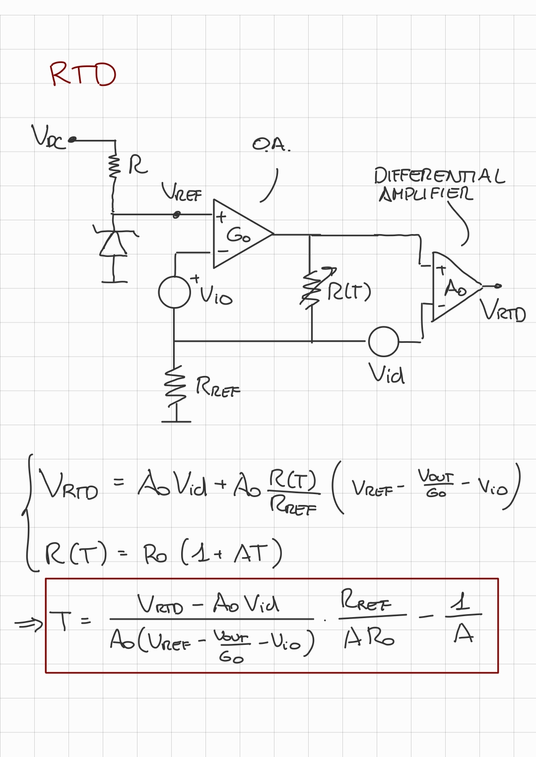
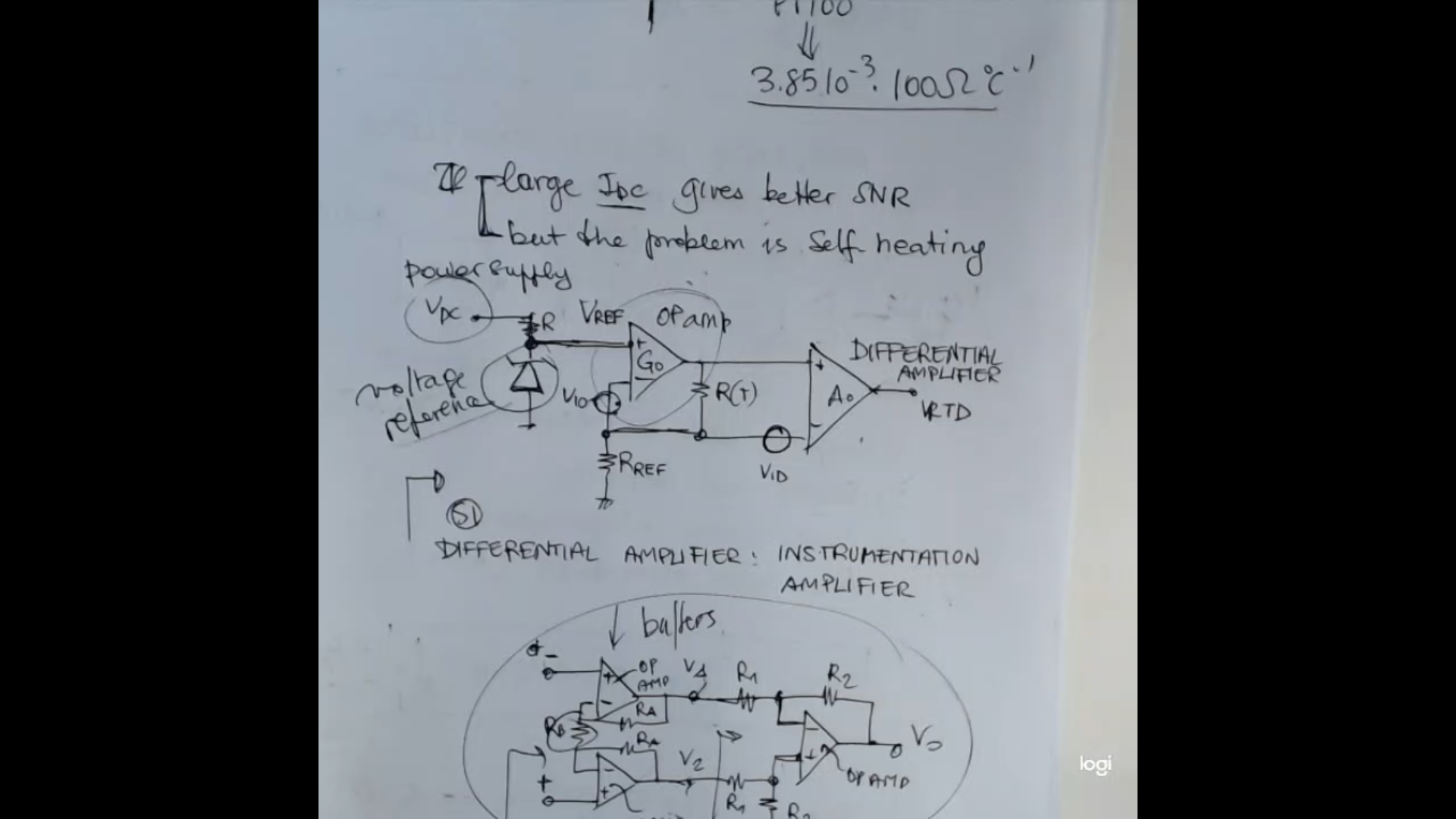
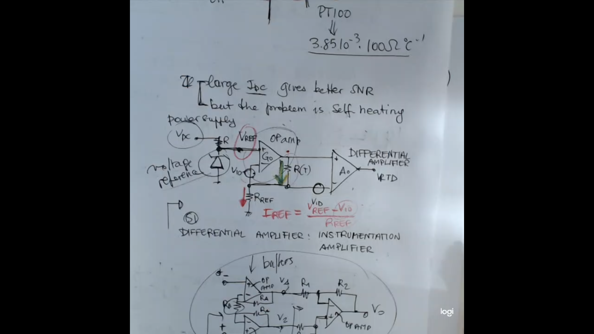
- This is the circuit:
- Here’s it the circuit with numerical values (not with real world values tho):
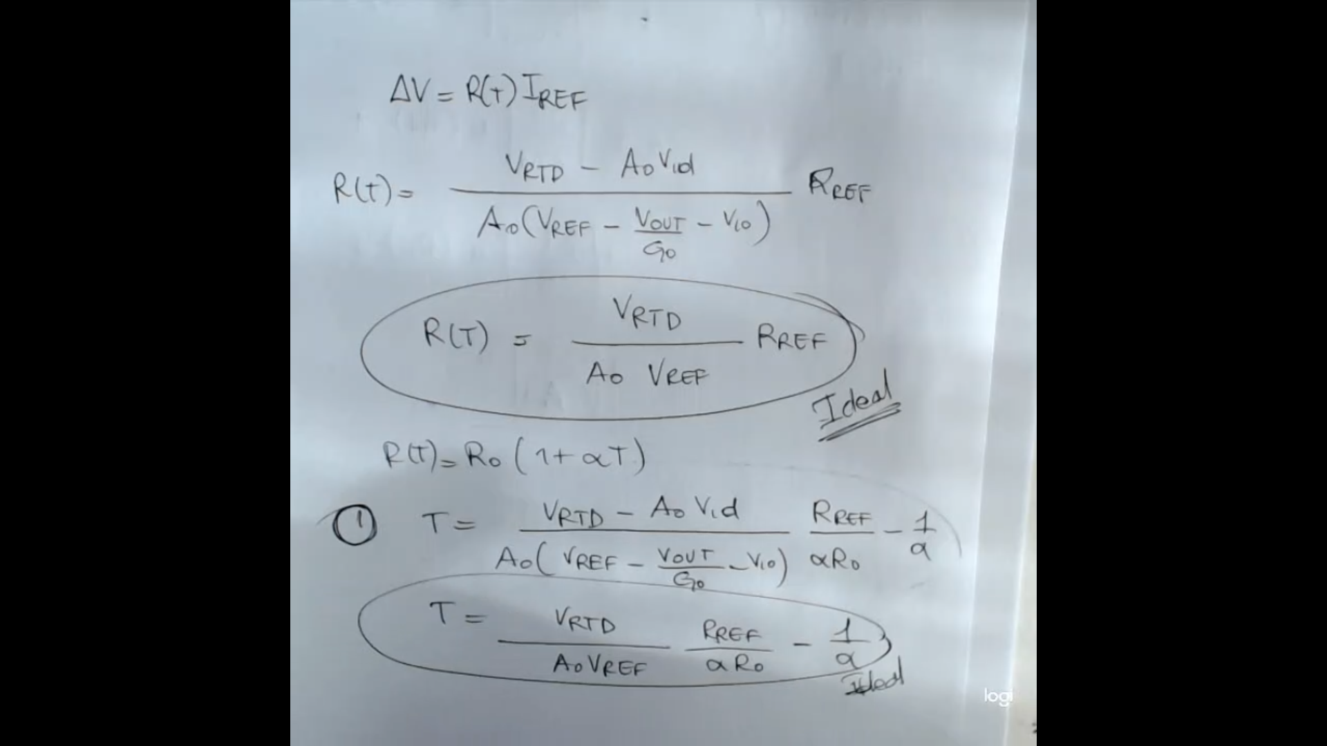
- So if we calculate the output of this circuit it will be:Or it can be rewritten as:
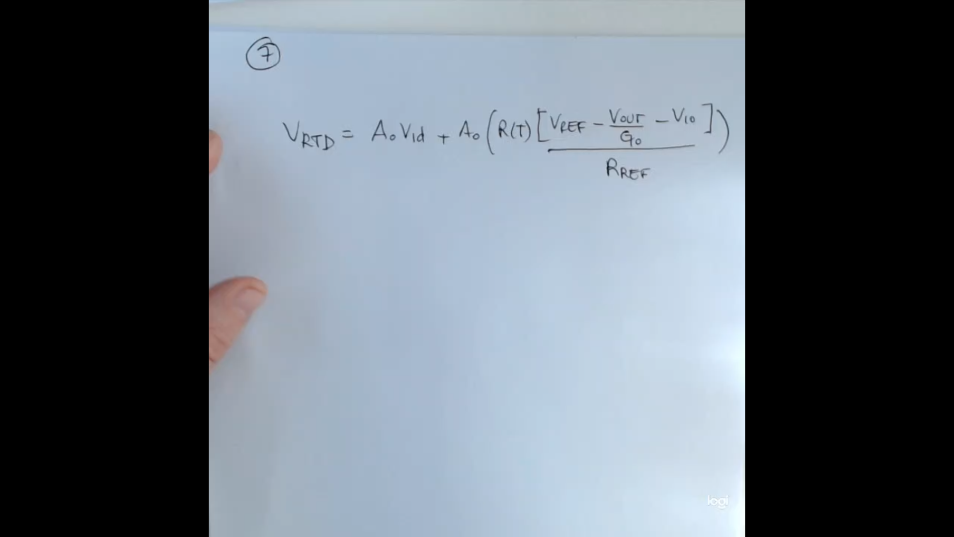
- ==NOTE: The professor found another formula, where it also conisdered the gain of the A.O., so a formula also depending on ==.
This is a simpler formula, where I considered and , so that it can be remembered more easily.- The complete formula would be:Where is the output of the A.O.
- Rememebr that we can see , using the Calendar Van Dusen Equation.
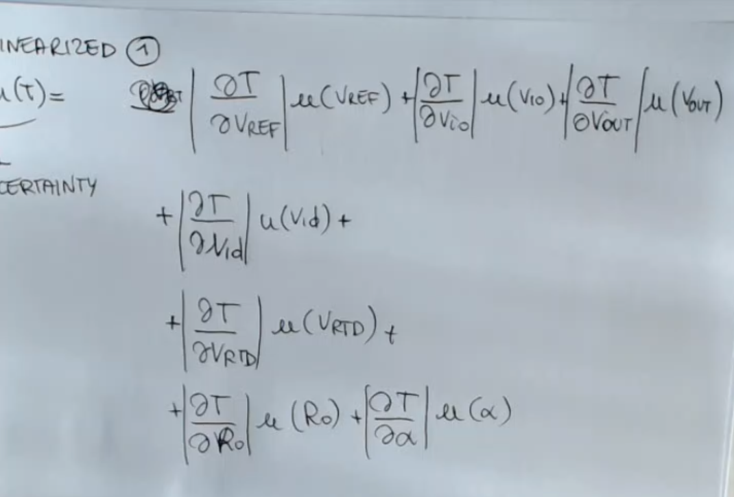
- So the complete formula for this RTD circuit depends on:
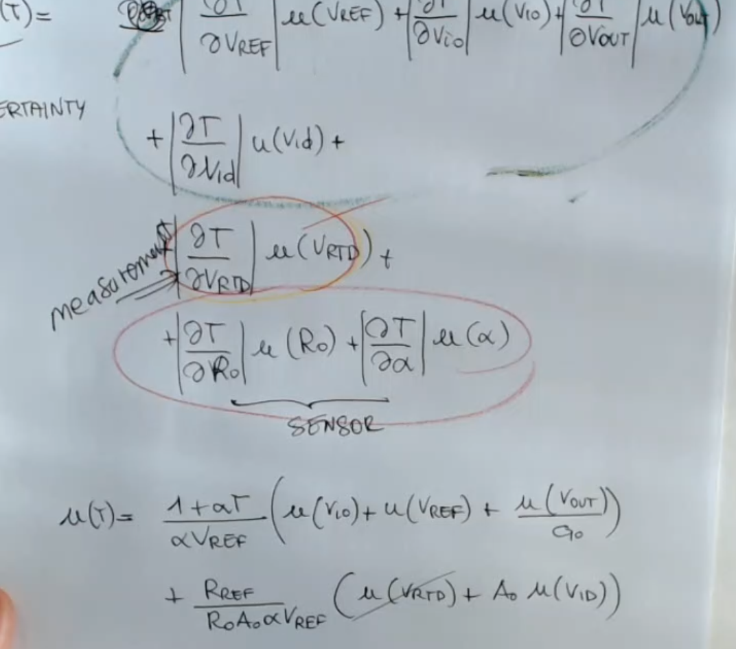
- So each of this parameter bring an uncertanty: ), , , , we can define the combined unceranty, or uncertanty on the measurament as:
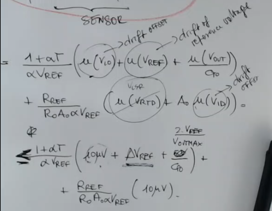
- Here are some real world values and names for some of this uncertanties:
- : “drift of the reference voltage”.
- : “drift offset” for the PT100 it is about .IMPORTANTE
- : “drift offset”.
- or : “Voltage at the Least Significant Bit”.
- So if we perform some calculations we obtain that:
- Circuit (With 2 A.O.):
In this Circuit the output is capped at V, that is the source voltage of the amplifier (), so it does not depend on the sensor, you need a differential amplifier, with limited gain.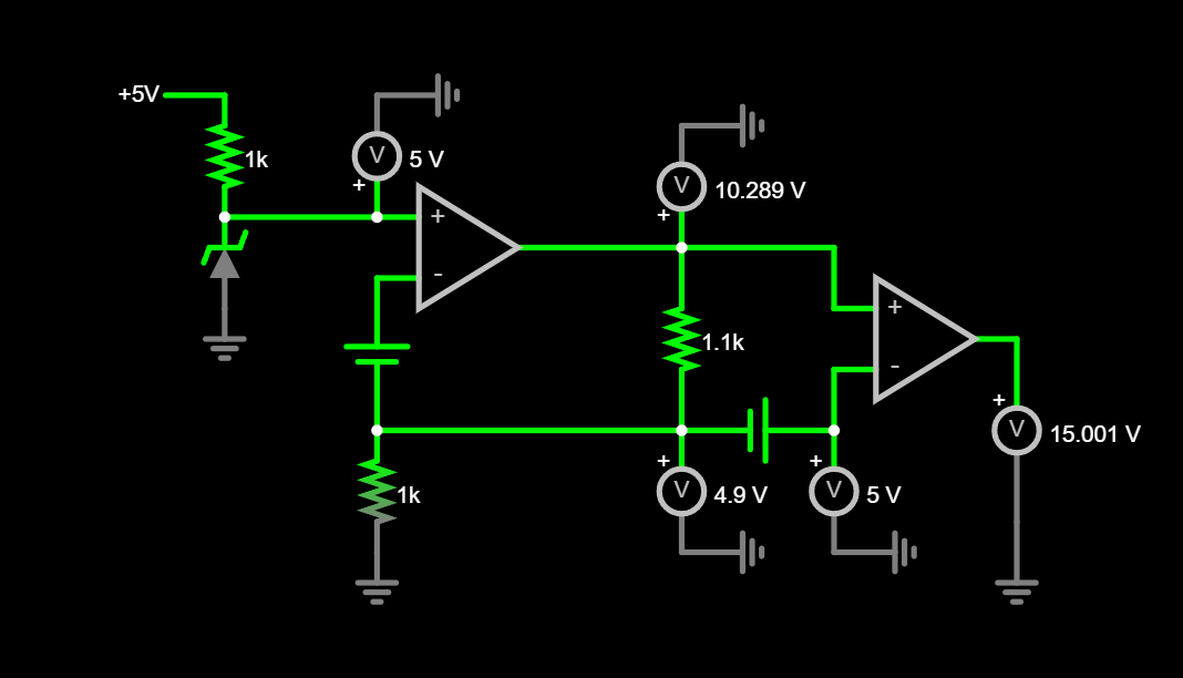
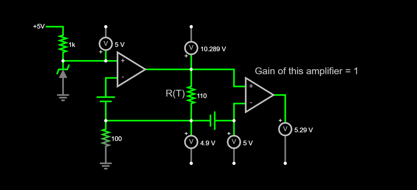
- Circuit (With an A.O. and an Ideal Differential Amplifier):
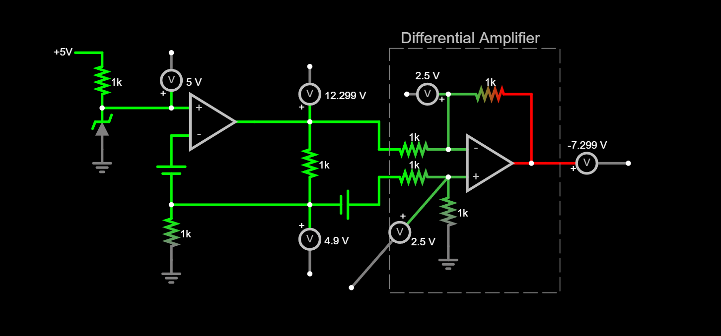
- Circuit (With an A.O. and a Non-Ideal Differential Amplifier):

Professor’s Notes
- The formula for , i don’t think it’s correct.NOT_SURE_ABOUT_THIS
All Quantities Contributing to the Uncertainty