List of things to memorize:
SaM - Front-End Electronics • Read-Out Electronics
Link to original
- SaM - Voltage Supply vs. Current Supply
- SaM - Accuracy of the Complete Measurement System
- SaM - Single Input Amplifier
- SaM - Differential Amplifier
- SaM - Instrumentational Amplifier
- Read-Out Electronics for AM and FM Circuits:
- SaM - Front End for an Eddy Probe
SaM - Voltage Supply vs. Current Supply
- Voltage source or supply:
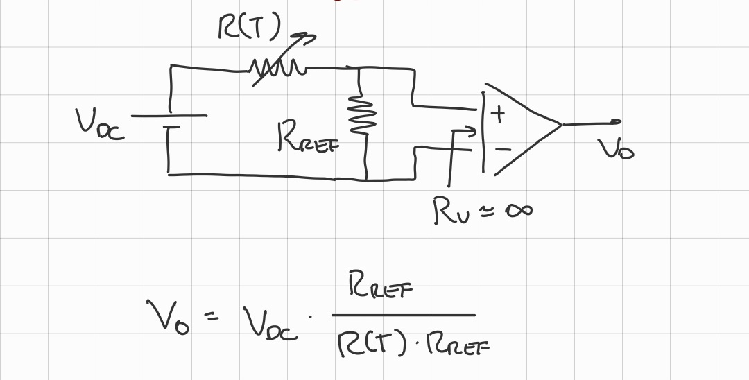
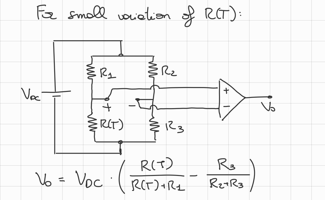
- Using a resistive bridge:
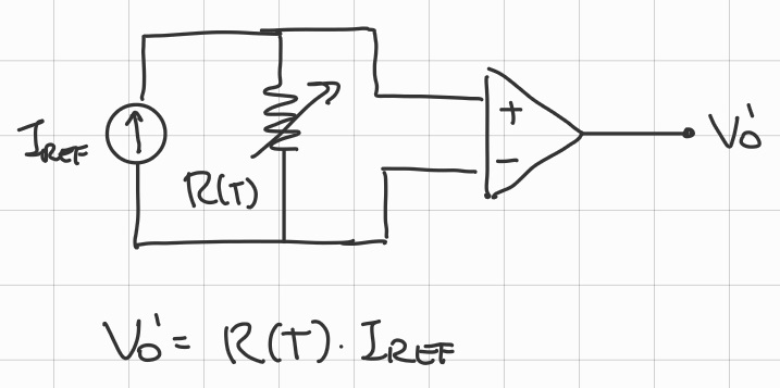
- Current source or supply:
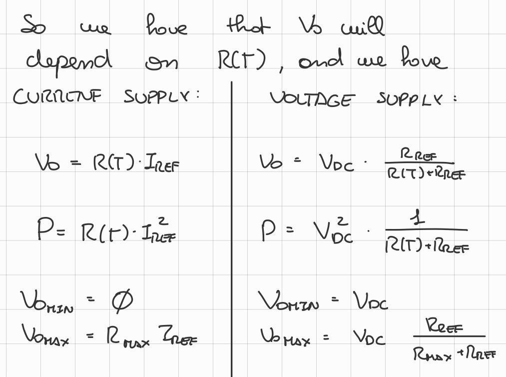
- Difference between the two:
SaM - Accuracy of the Complete Measurement System
- Complete Measurement system:
- Simple example using the PT100 sensor:
- Accuracy of the complete system:Where:
- : nominal resistance of the PT100 sensor.
- : Calendar Van Dusen coefficient.
- : open loop gain of the operational amplifier.
- : current source.
A higher current improves the SNR (Signal to Noise Ratio), however it can create a self-heating problem.
Link to original
/../../Notes--and--Images/Pasted-image-20231120190224.png)
/../../Notes--and--Images/Pasted-image-20231120191120.png)
SaM - Single Input Amplifier
- Representation:
- Usually an A.O. with one of the two inputs connected to ground:
Link to original
/../../Notes--and--Images/Pasted-image-20240116233210.png)
/../../Notes--and--Images/Pasted-image-20240116233538.png)
SaM - Differential Amplifier
A differential amplifier output functions depends only on the difference: Here’s an example:
Link to original
/../../Notes--and--Images/Pasted-image-20230626201332.png)
/../../Notes--and--Images/Pasted-image-20230626201359.png)
/../../Notes--and--Images/Pasted-image-20240131124912.png)
SaM - Instrumentational Amplifier
- Formula:
Don’t know if it is a requested knowledge for the exam, here’s some information on the instrumentational amplifier “INA128”
Link to original
/../../Notes--and--Images/Pasted-image-20231004153316.png)
SaM - Readout Electronics for Capacitive Sensors (FM & AM Oscillators)
- We need to distinguish between:
- Low frequency signals or DC signals.
Read-out for low frequency signals:
- FM: Frequency Modulation which uses a grounded sensor.
- AM: Amplitude Modulation which uses an unreferenced sensor.
- High frequency signals.
Read-out for high frequency signals:- For low frequency signals, we will need an AC exitation.
The frequency of the excitation () has to be much larger than the maximum signal frequency (), it should not be a problem since it’s a low frequecny signal.
Since the signal varies slowly, the capacitance takes a value which is constant for a long time.
This time is enough to allow the loss of the charge which is stored in the capacitors due to the parasitic resistances.
Link to original
SaM - FM (Frequency Modulation) Based on Oscillators
- Using a square wave oscillator:
- Formula:
- Frequency of an FM modulated signal:
- FM modulation using an integrator:
(For instance if I have which is a slowly growing invariant signal, then the frequency would increase a litte over time.)- Bandwidth of the FM modulated signal:
Where:
- .
- And comes from: .
- Since FM transforms a the physical input variation into a variation of frequency, it is a very robust solution to reject noise.
- Complete FM Circuit:
/../../Notes--and--Images/Pasted-image-20230719105215---Copia-1.png)
- The sensor is part of the oscillator.
- The FM Demodulator gives as output a voltage related to the frequency in input.
- Real World Measures:
- FM is used for signals which can be static but also they have a large bandwidth up to
- The typical value for is (much larger than the maximum signal frequency).
Link to original
/../../Notes--and--Images/Pasted-image-20230719105145-1.png)
/../../Notes--and--Images/Pasted-image-20230719105202.png)
/../../Notes--and--Images/Pasted-image-20230719105215.png)
SaM - AM (Amplitude Modulation) Based on Oscillators
- Simplest circuit for AM (Amplitude Modulation):
- Output:Where:
- General formula of the AM modulation:Where:
- Spectrum analysis:
- Good circuits for AM modulation:
- Current or charge amplifiers.
- AC bridges.
- Voltage dividers.
Link to original
/../../Notes--and--Images/Pasted-image-20230719105223-1.png)
/../../Notes--and--Images/Pasted-image-20230719105232-1.png)
SaM - AM Modulation with 2 Sensors • Carrier Amplifier
- Circuit:
- Sensors:
- Output:
- Final formula:
- For :(If I select a value for too large with respect to than I’ll have a very small signal, not good).
(Since this is an FM modulation, we will lose sign of ).- Bode graph:
- Complete circuit with sign-recovery:
- Real World Measures:
- , also
Link to original
/../../Notes--and--Images/Pasted-image-20230719105256-1.png)
/../../Notes--and--Images/Pasted-image-20230719105325.png)
/../../Notes--and--Images/Pasted-image-20230719105428.png)
SaM - Switched Capacitors
- Circuit:
(It can be used to increase the capacitance value, with respect to the sensor’s capacitance, without changing the actual capacitance)- Workings:
- START : : closed, so that we start from .
- CHARGES: (: ON, : OFF, : OFF).
- SHARE ITS CHARGE WITH : (: OFF, : ON, : OFF).
- repeat (2.) and (3.), times.
- Output at each step, relative to previous step:
- Absolute output formula:Where:
- Graph:
(If I limit the measurement ratio to , opprotunaly choosen, I will remain in the linear range)
Link to original
/../../Notes--and--Images/Pasted-image-20230719105612-1.png)
/../../Notes--and--Images/Pasted-image-20230719105635.png)
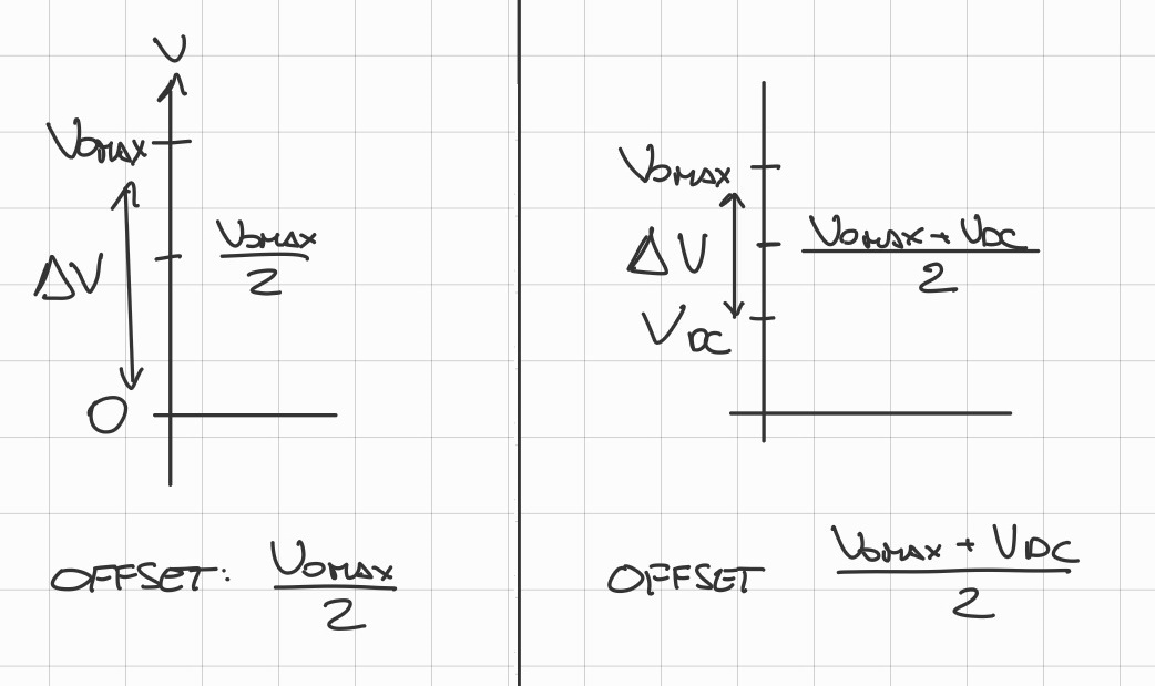
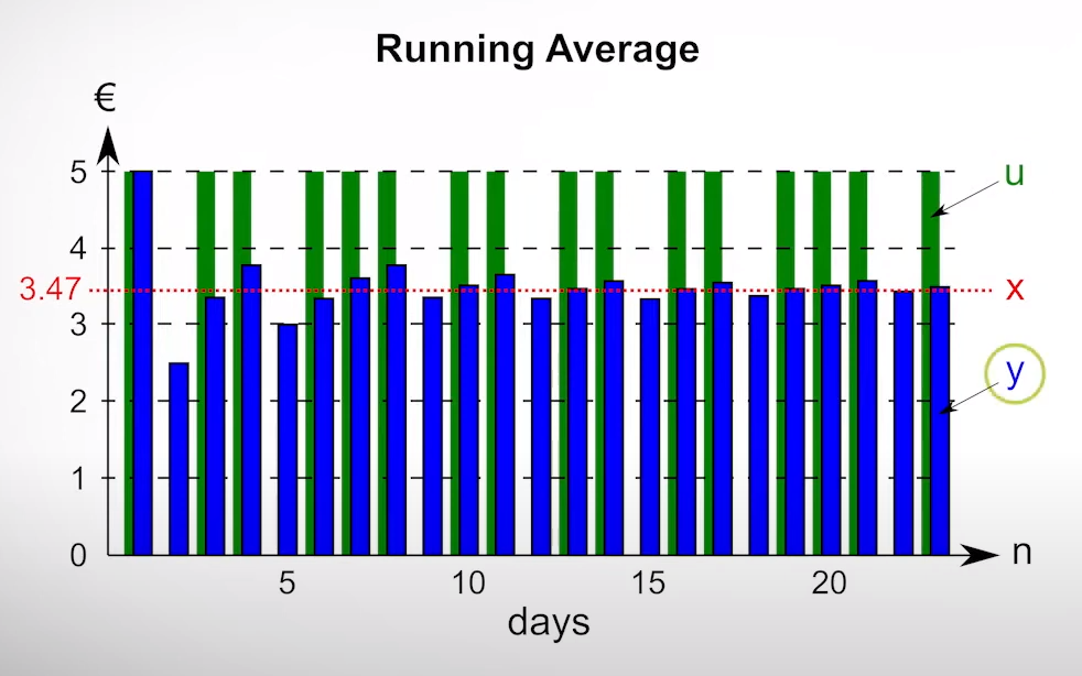
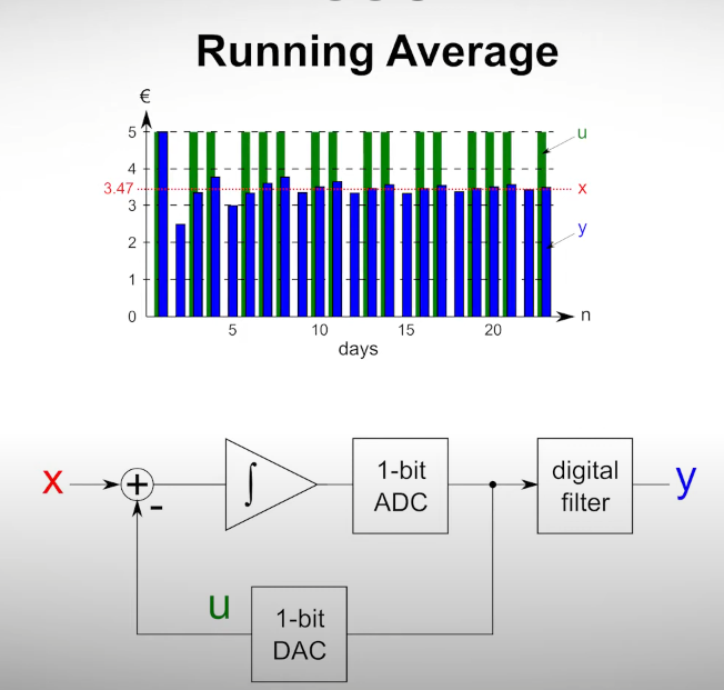
SaM - Sigma-Delta Converter (AD Converter)
- Structure:
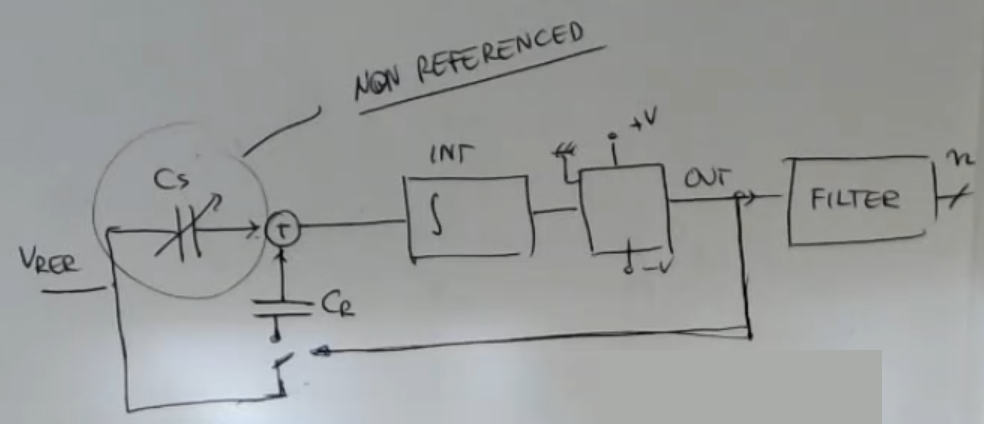
- For this converter you need a not-referenced capacitive sensor.
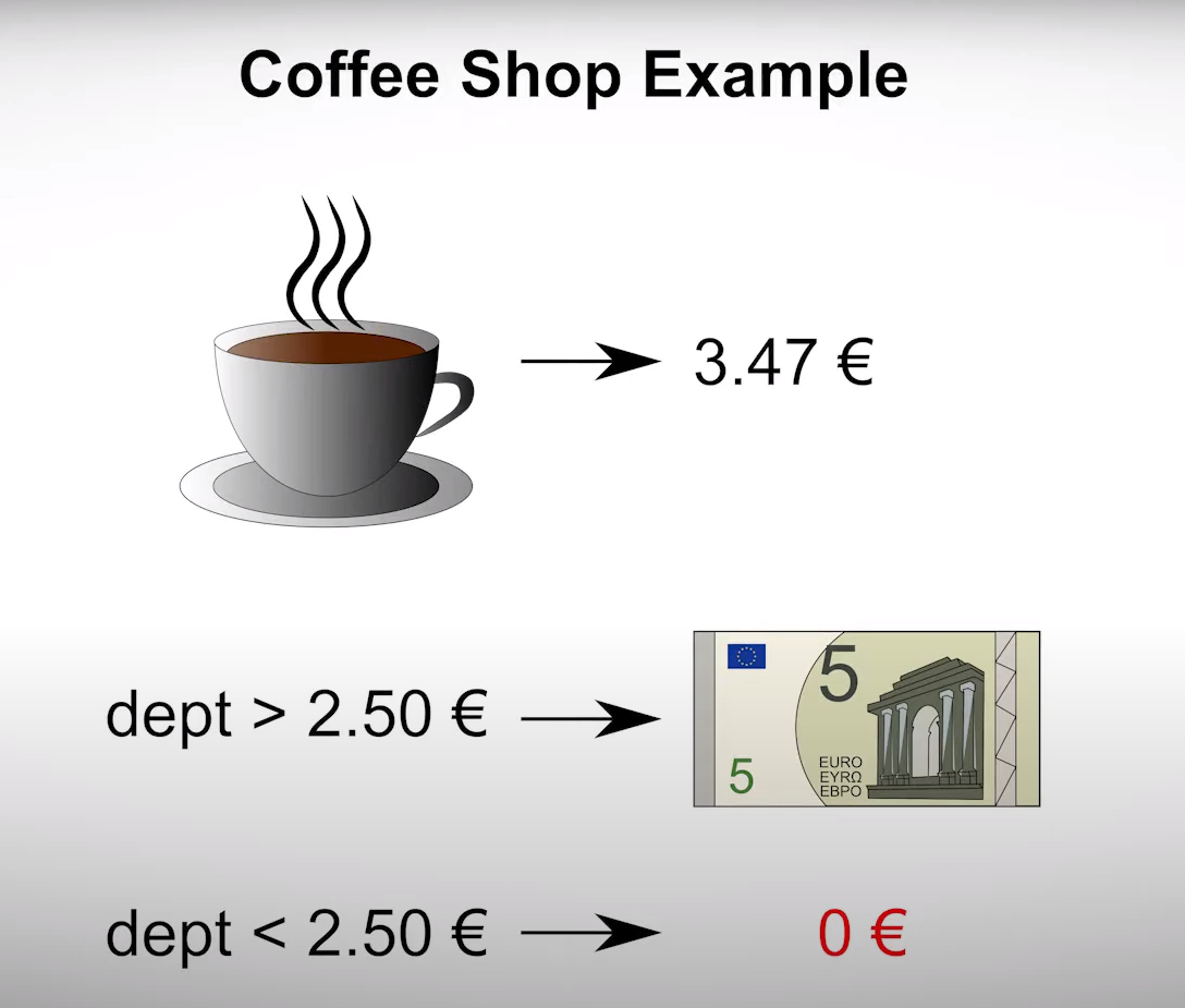
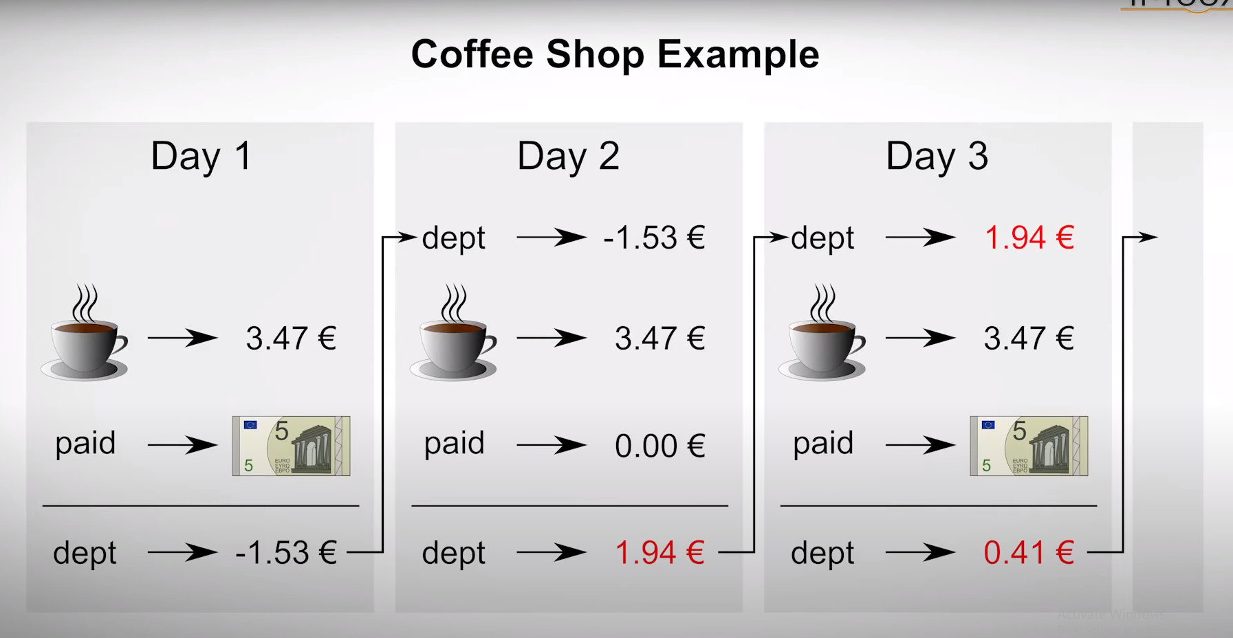
- Simplified formula (based on the coffee shop example):
- Coffee shop example:
SaM - Front End for an Eddy Probe
- This circuit uses an Eddy Probe, to represent it I use the symbol of the inductance with 2 lines in front ():
- We need a carrier amplifier, a synchronous demodulator, and a logarithmic amplifier.
- In this case, there is another probe (), which is not exposed to the target, it’s not facing the target, and it’s in an enclosed situation.
It is used only to compensate the temperature effect on the actual sensor, since the coil and also the resistance are sensitive to temperature.
Link to original