Remeber:
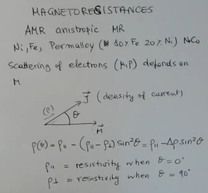
==The Anisotropic Magneto-Resistance (AMR) is a phenomenon in which the electrical resistance of a material depends on the direction of an applied magnetic field==:
- It is usally present in ferromagnetic materials.
- We have seen some example of materials that present AMR, like: Ni, Fe and Permalloy ( Fe + Ni)IMPORTANTE
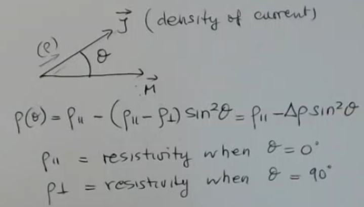
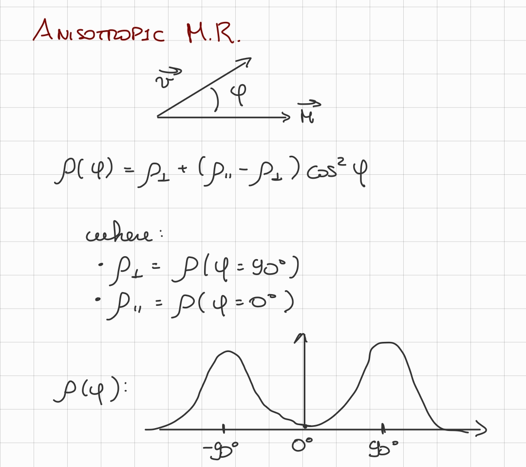
- The formula that governs the AMR is:Where:
- is the resisitivity when .
- is the resisitivity when .
- is the angle formed by and , where:
- is the electric current density vector.
- is the total magnetization vector, accounting for the external magnetic filed , and for the magnetization of the material .
We need to define an easy axis, which will in the same direction of (the magnetization of the material):
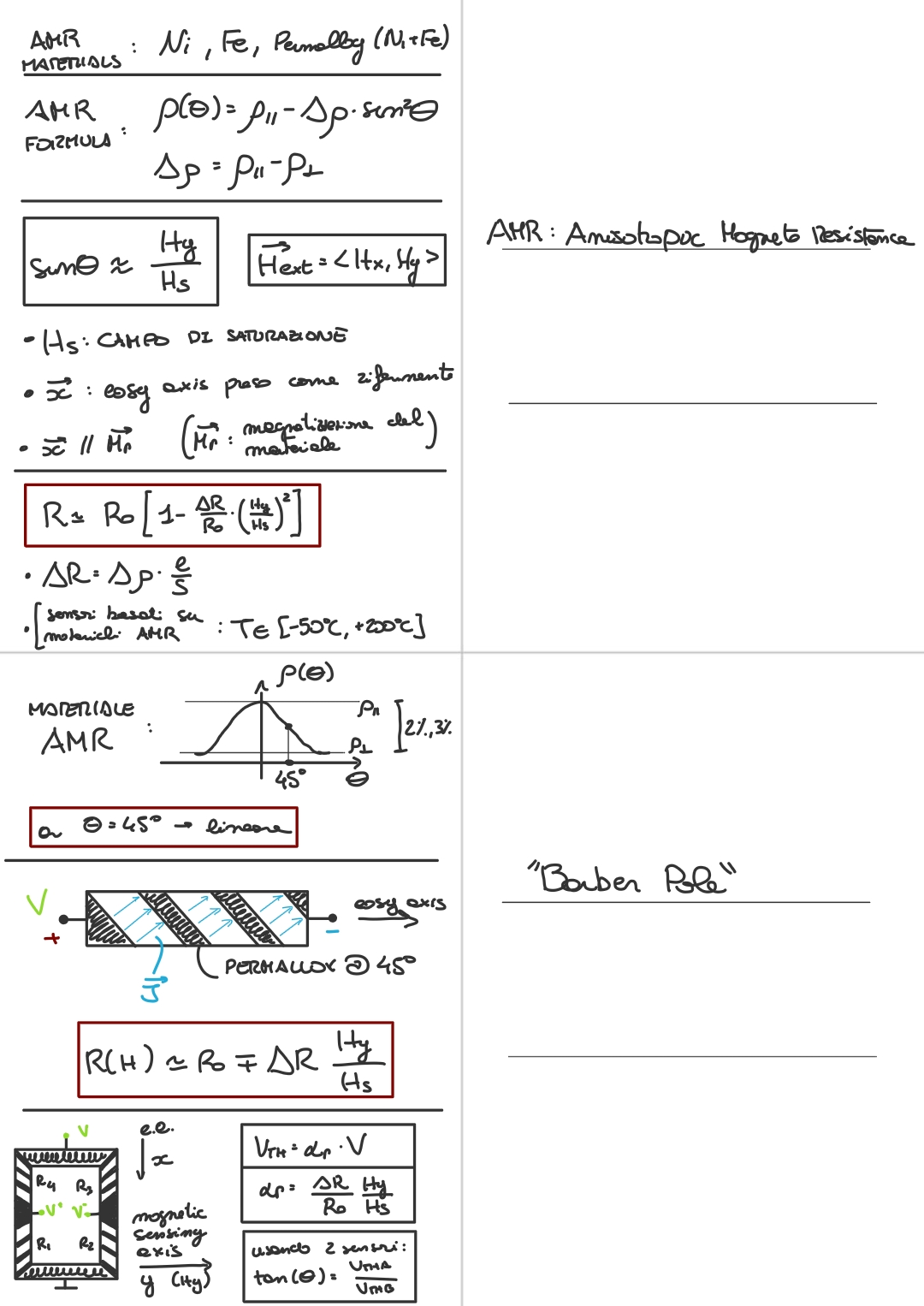
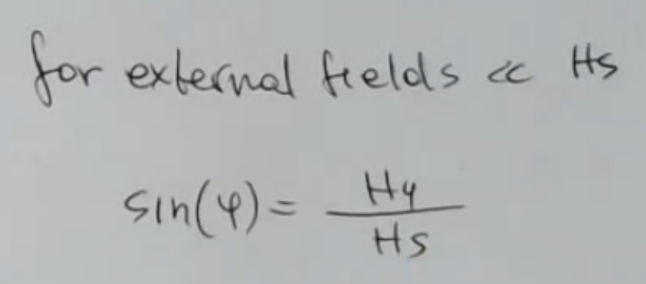
If we have that than we can approximate:Where:
- is the saturation field, it is a property of the material.
We usually use thin films of material for AMRNOT_SURE_ABOUT_THIS (Why?)
So if we calculate the AMR formula using the approximation found for , we find that:Which is still non-linear. If we wish, we could transform the formula into resistance, instead of resisitivity:In this case remember that:
- Where: .
If we plot the graph of given :
We notice that for we have an almost linear graph. So we can linearize our passive sensor in 3 ways:
- By adding an external “biasing field”.
So we operate as to fix the opearitional range around the 45° point, by injecting a field.- We rotate the current with respect to the easy axis. (most used)
Not discussed
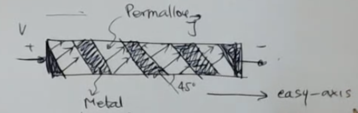
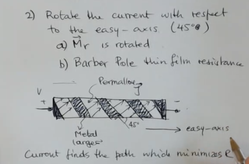
Let’s see how we can rotate the current: We can create a “barber pole” using two different conductors (for example a “Permalloy” and Metal) and we bond them with this structure:
- This way the current (since it finds the path that minimizes ) will be “tilted” by 45° with respect to the easy axis.
- We can mount barber pole like a resistive bridge to form a “Honeywell”, more on that later.
- This way we will have a linear behaviour defined like so:Where: , so we can say that:Remember this is still under the hypothesis that .
We can also stress that obviously if here I have put a "", and the reason is that this minus or plus depends on the easy access direction.
If we apply a large magnetic field to a barber pole, it could change the sensitivity, and also the sign of the sensitivity of the device, this is know as “Flipping Effect” (or “Hysteresis”NOT_SURE_ABOUT_THIS ) To solve this problem we can apply a reverse and stronger external field.
Obviously since this is a magnetic material, we have the most important problem of hysteresis. That means that under the application of a high enough external magnetic field, the original magnetization can change. NOT_SURE_ABOUT_THIS (It is the same problem as the flipping effect, it just changes name)
- ==This sensor works properly for weak external field==.
- The sensitivity is large for these devices and also the frequency range can be large as well.
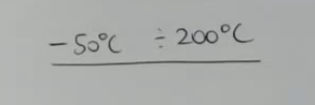
- The temperature span is approximately , so it is very large.
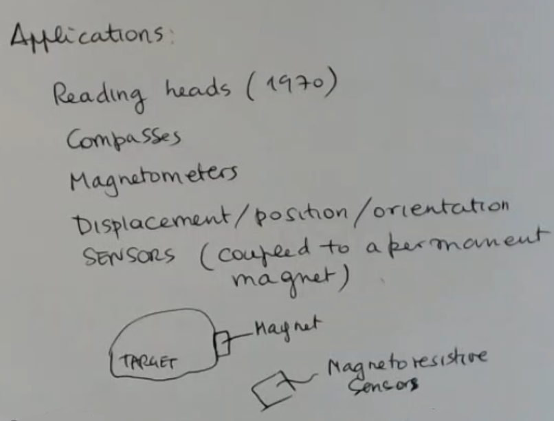
Applications for Magnetoresistances:
If we mount Barber pole in a single package we can create a full bridge:
The final formula for this strucutre is:NOT_SURE_ABOUT_THIS Where:
- is the output.NOT_SURE_ABOUT_THIS
- is the relative sensitivity, and for this structures it is usually .
- is the input voltage.
We can also calculate the relative sensitivity as:NOT_SURE_ABOUT_THIS Remember that:
We can also pack more honeywell in a single chip or package to create magnetoresistor that measures magnetic fields in more than one dimension, for example:
There are also other kind of devices, similar to this one, which are made to operate with larger fields, like magnetic position sensors*:
Here we have that we can measure the angle of the magnetic field as:Where:
- refers to the bridge sensing along the axis.
- refers to the bridge sensing along the axis.
Memory Card
Index
- Anisotropic Magnetorestance
- Thin Film Geometry Variation
- Linearization of a Magnetoresistive Sensor
- Flipping Effect
- Conclusion on Magnetoresistive Sensors
- Applications for Magnetoresistances and Hysterisis Problem
- Honeywell
Anisotropic Magnetorestance
- These devices are used for measurement of the magnetic field of the earth, so for compasses.
- ==Usually they are based on the AMR (Anisotropic Magneto Resisitivity)==.
- We find for this kind of materials, that the scattering of electrons, therefore the mobility () and resistivity () depends on the vector , which is the magnetization or the magnetic moment.
- In general for this material, we find that if I have the certain direction for the vector , and (current density vector) ⇒ the resisitivity , is related to this angle by this equation:
- or when there in’t any applied external magnetic field ⇒ so I think of a permanent magnet.
- First of all, we call the direction of this permanent magnetization “easy axis”, so i take as reference () this easy axis.
- if I apply an external magnetic field, then the overall magnetic moment will rotate (by an angle ).
- : This is the magnetic field component in the horizontal () direction.
- : This is the magnetic field component in the vertical () direction.
- is a property of the material, and it is called saturation field.
- What is the Saturation Field? (ChatGPT)
- The saturation field, also known as the saturation magnetization or saturation magnetic field, is a characteristic property of a ferromagnetic material.
It represents the strength of an applied external magnetic field at which the material becomes fully magnetized.
In other words, it's the point at which the magnetic domains within the material are aligned in the direction of the applied field, and further increases in the field strength do not result in additional magnetization.
- The saturation field, also known as the saturation magnetization or saturation magnetic field, is a characteristic property of a ferromagnetic material.
- : This is the magnetic field component in the vertical () direction.
- is a property of the material, and it is called saturation field.
Simarly we have said that:
Thin Film Geometry Variation
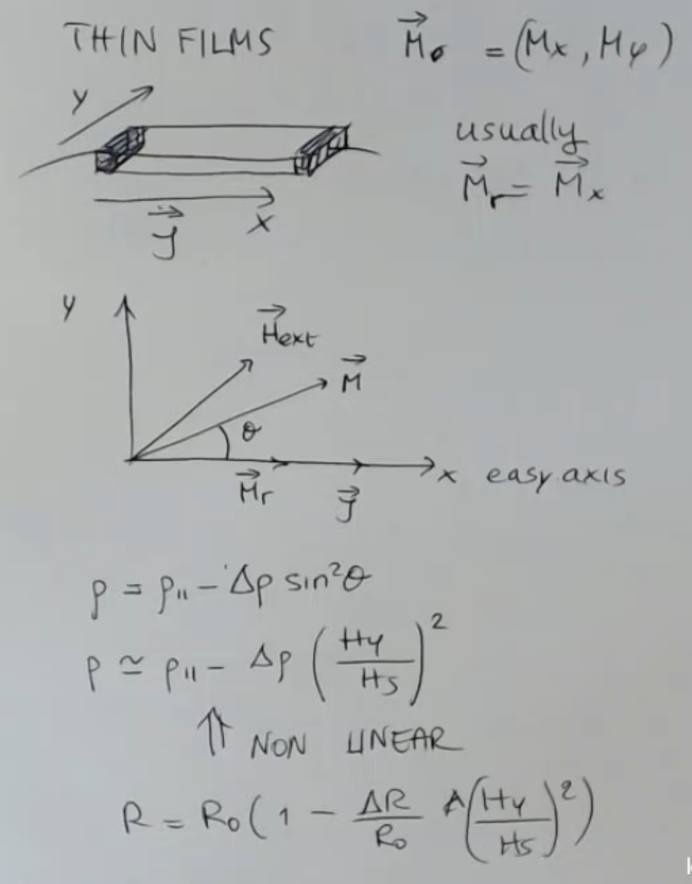
- So the resistance of the thin film changes like so:
- In this case remember that where .
Graph of how the fucntion changes with .
Linearization of a Magnetoresistive Sensor
So there is a linearization of the sensor. And this can be done in 3 ways:
- By adding an external “biasing field”.
So we operate as to fix the opearitional range around the 45° point, by injecting a field. - We rotate the current with respect to the easy axis. (most used)
Not discussed
Biasing Field: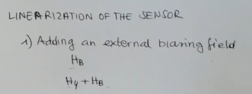
- : external “biasing” field.
Rotate the current:
- Usually we do something different, we rotate the current with respect to the easy axis.
And this rotaion has to be close to 45°.
And this can be done in 2 way:- Magnetize the the film material with a different angle with respect of its axis. So is rotated by applying a very strong field during the position for instance.
- But the best solution and the one which is commonly used, is to build a thin film resistance which presents a special structure which is called “barber pole”.
So this is the thin film, and what happens is that actually the film is made of different domains:
So these strips here represents different materials:
Black should be metal metal like gold, so large conductivity.
This is the permalloy for instance.
The angle should be 45°.
⇒ So If we introduce a metal target, and a permalloy, in this disposition, we have that the current (indicated by current density ) will “travel in a angle” as show in the picture, that is due to the fact that “current finds the path which minimizes “.
So we have a linear behavior: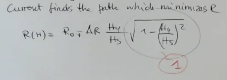
- And this is true under certain hypothesis for instance, the field (especially the component ) has to be not so large compared to the saturation .
⇒ So the range is limited by the material characteristics. - And we can also stress that obviously if here I have put a "", and the reason is that this minus or plus depends on the easy access direction.
Flipping Effect
The application of large external field can affect the behavior of a Barber Pole, it can change the sensitivity, and also the sign of the sensitivity of the device. This phenomenon here which occurs under strong external fields is called the flipping effect. Sometimes the magnetization can be reset, so the flipping effect can be solved by applying a reverse and stronger external field.
Conclusion on Magnetoresistive Sensors
- ==This sensor works properly for weak external field==.
- The sensitivity is large for these devices and also the frequency range can be large as well.
- The temperature span is approximately , so it is very large.
Applications for Magnetoresistances and Hysterisis Problem
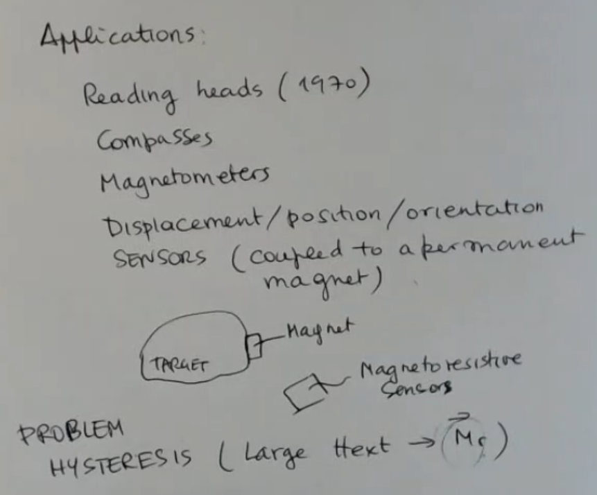
- Obviously since this is a magnetic material, we have the most important problem of hysteresis.
- That means that under the application of a high enough external magnetic field, the original magnetization can change.
Honeywell
To conclude, let’s see the devices which exist based on these kind of sensors here. And so I refer to some devices of the “Honeywell”.
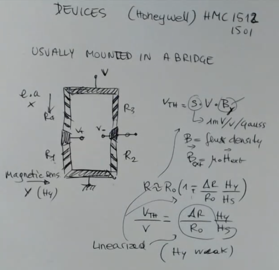
- Where:
- : ???TODO
- : flux density, ember that actually we sense along the axis.
- Each resistence is formed by a Barber Pole strucure like we have seen before.
- This is magnetic sensitivity axis, which was , is in this direction here:
- As we have said in theory: we are operating with weak magnetic fields, and thanks to the barber poles which ==rotate the current at ==
⇒ We can linearize everithing.
To measure the magnetic field in more direction we can just mount more sensors on the same chip:
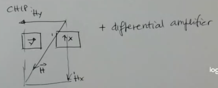
- One which sens along , and the other which is mounted as to sense the component of the field.
There are also other kind of devices, similar to this one, which are made to operate with larger fields:
- Where:
- refers to the bridge sensing along the axis.
- refers to the bridge sensing along the axis.
- : sensitivy.
They have the same sensitivity, because they are the same devices only rotated.
- ==We stress the dependency on this time, because here is the non-linearized version==
- I write better the formula for :
- At the end by evaluating the ratio of these two voltages we can find that it is actually the tangent of the angle .