Remeber:
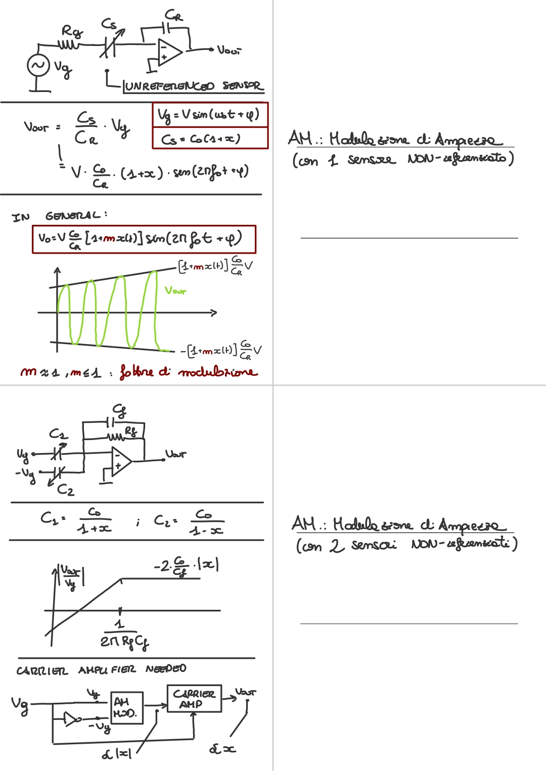
We have said that for reading a capacitive sensor, if the measured quantity varies slowly, we need a special modulation of the signal. We have seen AM modulation and FM modulation, let’s see now another option. Like for AM modulation, we will use ungrounded or unreferenced sensors.
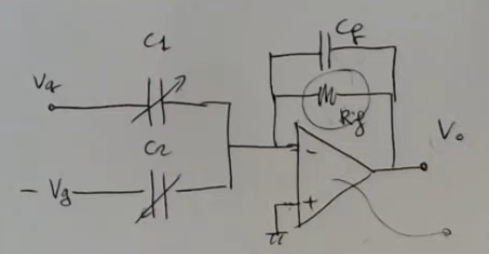
This time we’ll use two capacitive sensors, mounted on a structure like this:
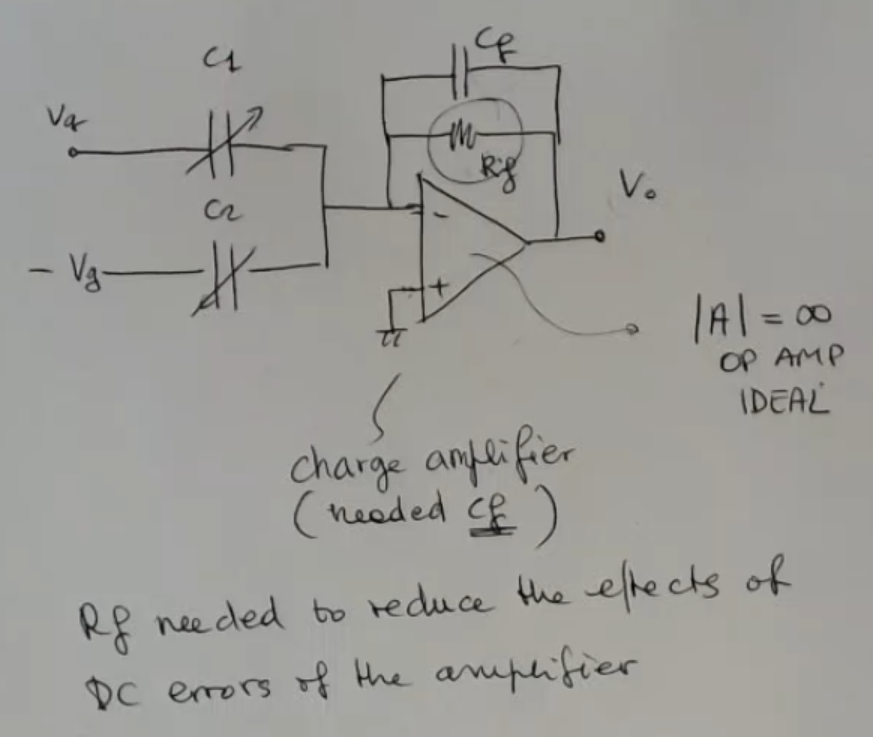
- (ideal op amp).
- is needed to reduce the effects of the DC errors of the amplifer.
- and are capacitive sensors.
We will model them as:NOT_SURE_ABOUT_THIS- The output function is:Where:
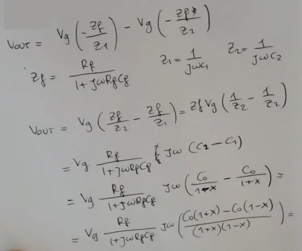
If we perform the calculations, we find:Where:
- , also
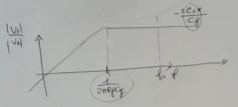
This will be the response of our circuit:
- I have considered constant in order to be able to study everything using these simple equations in the frequency domain.
⇒ So I need to consider that the frequency of the input is much larger than the maximum frequency of the signal, such that I can consider this quantity static during the analysis:- If I select a large value for this resistance , then I can select the I prefer.
- Also I have another constraint, if I select a value for too large with respect to than I’ll have a very small signal.
⇒ So I’m obliged to select this value small enough to give enough sensitivity.- Even if I take extreamly big, the output will still be (approximated):
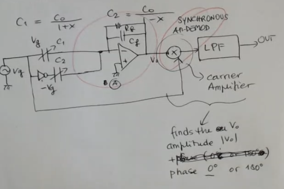
If we use this circuit, ==we will lose the sign of == in the output, since the output is a sinusoidal, while is a scalar value, we will see an example on this later. We need to recover the sign of , which is the same as Therefore, we need a circuit which is able to do two things:
- ==Finds the output amplitude ==.
- ==Being able to recover the phase, and distinguish if I have a or ==.
Here’s the complete circuit, that can also recover the sign of , using a carrier amplifier:
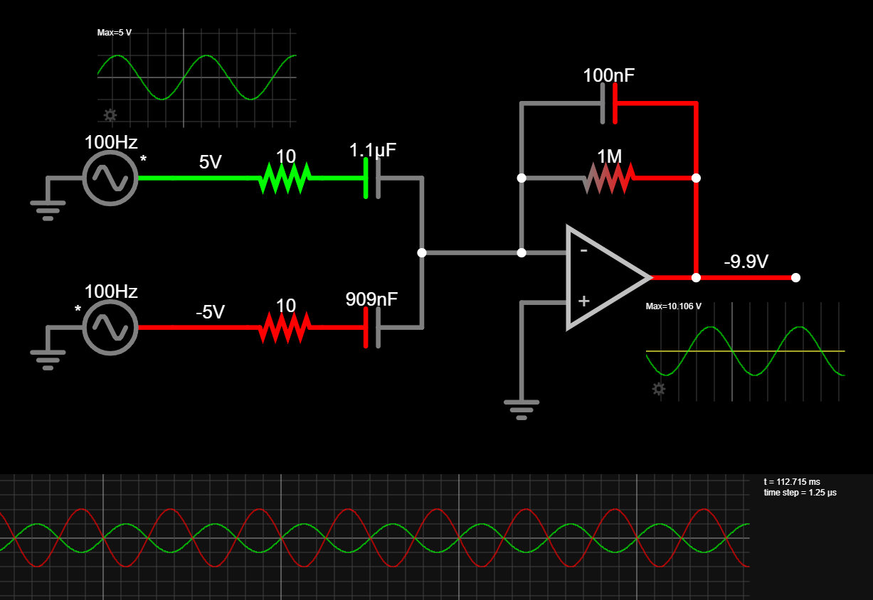
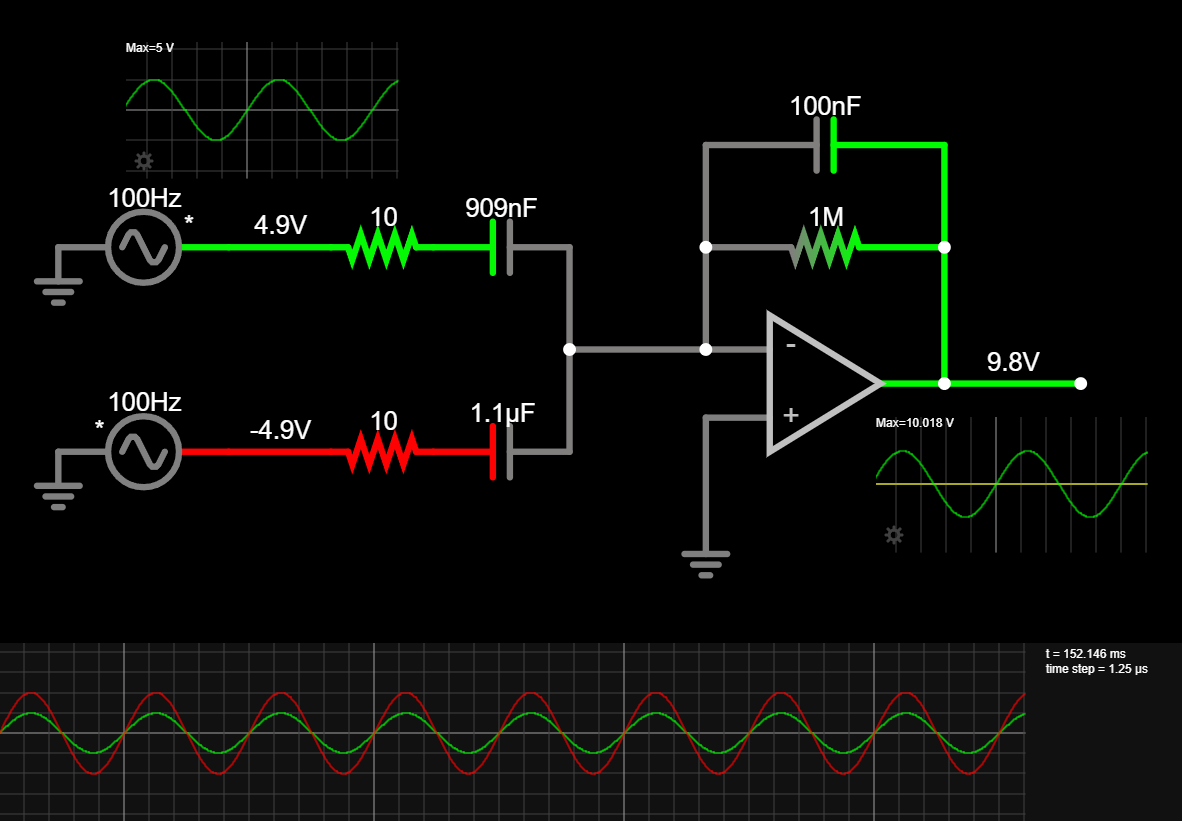
Here’s some interactive circuits:
Memory Card
If we take (which for proximity sensor should often be the case) we can simplify: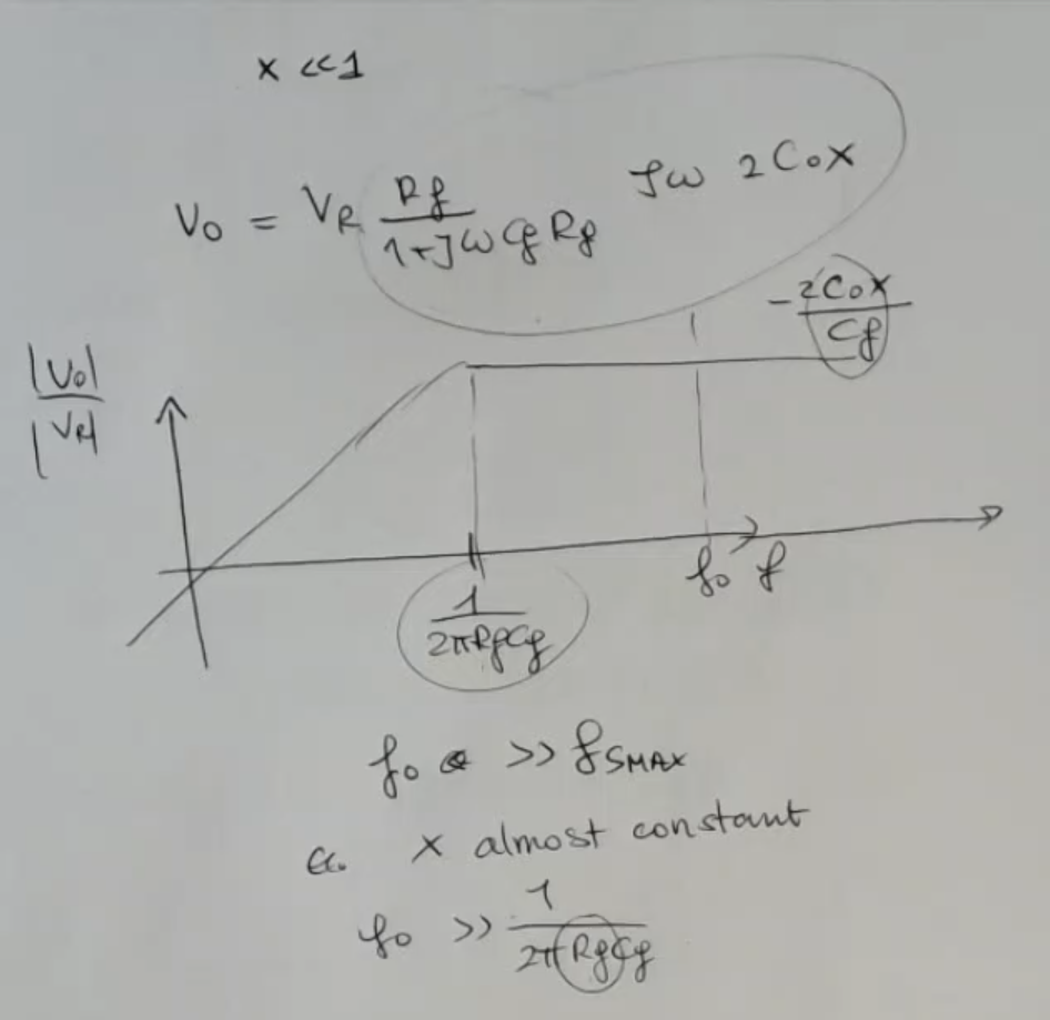
- I have considered constant in order to be able to study everything using these simple equations in the frequency domain.
so I consider that the frequency of the input is much larger than the maximum frequency of the signal, such that I can consider this quantity static during the analysis.
Actually, we know that this change. - So if will select a large value for this resistance in order to let me select the I prefer.
- Tho I have another constraint, if I select a value for too large with respect to than I’ll have a very small signal.
⇒ So I’m obliged to select this value small enough to give enough sensitivity. - Even if I take extreamly big, the output will still be (approximated):But I do have some liberty on (I do can choose big as I want, whithin some limits of course,NOT_SURE_ABOUT_THIS )
- And you see that if changes its sign, what happens is that obviously the amplitude remains the same.
But the output will have a phase which is different with respect to the input wave, which is . - Therefore, if we go back to the complete circuit, in this case, we need a circuit which is able to do two things:
- ==Finds the output amplitude ==.
- ==Being able to recover the phase, and distinguish if I have a or ==.