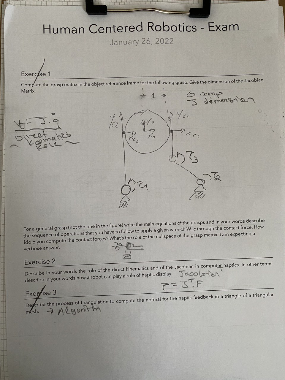
Compute the Grasp Matrix in the object frame for the following grasps. Give the dimension of the Jacobian Matrix.
For a general grasp (not the one in the figure) write the main equations of the grasp an in your words describe the sequence of operations that you have to follow to apply a given wrench Wc through the contact force.
How do you compute the contact force?
What’s the role of the nullspace of the grasp matrix?
(Exercise 1) First we define the contact pointsd1 and d2 with respect to the center of the object/the reference system of the object, so:d1=[1,0,0],d2=[−1,0,0]Then from these we define their respective screw matricies, so:S(d1)=0000010−10S(d2)=00000−1010Then we define the grasp matrix:G=1000000100010010−1010000001000−1001010Then we define the hand Jacobian, since we don’t have the dimensions of the arms, I’ll define them like so:b1=0b1y0,b2=b2xb2y0,b3=0b3y0As we can see the z axis is 0 for all of them, then like for the grasp matric we define the screw matrices for all of them:S(b1)=00−b1y000b1y00S(b2)=00−b2y00b2xb2y−b2x0S(b1)=00−b3y000b3y00Then we’ll constract the complete hand Jacobian:JT=00−b1y000000000000000b1y0000000000000−b2y00−b3y00000b2x000000b2y−b2x0b3y00The complete hand jacobian, will have dimensions: [9×6], if we were to reduce it, so by not considering the z component for the torques, since we can say that for construction of the manipulator τx and τy will be always 0, so if we write the complete formula:τ1xτ1yτ1zτ2xτ2yτ2zτ3xτ3yτ3z=00−b1y000000000000000b1y0000000000000−b2y00−b3y00000b2x000000b2y−b2x0b3y00F1xF1yF1zF2xF2yF2zWe can reduce this formula, by considering τ1x=τ1y=τ2x=τ2y=τ3x=τ3y=0, so:τ1zτ2zτ3z=−b1y000000000−b2y−b3y0b2x0000F1xF1yF1zF2xF2yF2zNow the reducedhand Jacobian has dimensions [3×6]. More generarly, given a general grasp, so we are talking about nc contact points (so d1,…,dnc). We want to apply a wrench WC through the contact force FC: 1. We define the screw matrices for all of them, so: S(d1),…,S(dnc) and S(b1),…,S(bnj) 2. We calculate the grasp matrixG:G=[IS(d1)……IS(dnc)] 3. We resolve the following formula to obtain the contact force to apply:FC=G#⋅WC+N(G)⋅ξDove: •G# indica la pseudoinversa di G. •N(G) è il nullspace di G. We need to say however that for these forces to apply, they need to be inside the friction cone, unless we are talking about an enveloping grasp, so that for N(G)=0 then the system has only has only one solution menaning that the forces need to be inside the friction cone, otherwise we would not have a grasp, and the object would slip, and with N(G)=0 we cannot change the friction cone, in any way. While for N(G)=0 we can change the ξ vector such that the normal forces with respect to the surface/plane where the contat points are, increase and so does the friction cone, so for N(G)=0 we can ensure the grasp. Also we have said that if G has max rank (more specifically rank=6) then we have a grasp that can move and rotate the object in every direction, since we can always find an FC such that:WC=G⋅FCNOT_SURE_ABOUT_THISIf the matrix was a square one the proof could be simple, since a square matrix with max rank is always invertible, but in this case we are talking about a rectangular matrix
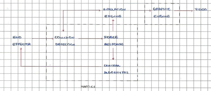
(Exercise 2) Let’s start with how we can describe a complete system for an haptic display, meaning a robot that takes in input the force we provide as users, and returns in output another force that we (users) feel, for example: we could feel a force with opposite direction to the one we gave as input. To do so, we have seen the simplified design of a simple haptic process: And we have defined “in mathematic terms” how it can do so:input→k⋅Δx→F→τ→outputSo the user moves the end-effector, the sensors measure this force, then we pass the data to a force response, such that we can decide/calculate how the end-effector should respond to this movement, then we pass this Fe to the control algorithm such that it can calculate the correct torque for each joint. To calculate the correct torques, we can use the Jacobian matrix, defined as:J=∂α∂Fx∂α∂Fy∂α∂Fz∂β∂Fx∂β∂Fy∂β∂Fz………Where: •α,β,… : are the angels of each joint (considering only revolutionary joints). •Fx is the function that returns the x-position of the end-effector, given the variuos linkers lenght (ρ1,ρ2,…) and angles (α,β,…), this is the role of the direct kinematics, meaning that if we know the angles of the joints and linkers’ lenght, we can always found the position of the end-effector. •Fy,Fz instead are for the y and z position of the end-effector, respectively. Then using this matrix we can calculate the torques, simply by applying the following formula:τ=JTFe
(Exercise 3) Given a triangular mesh of an object, we need first to identify the bounding box, so the smallest box that contains the triangle we want to ‘study’: So we start by checking it the end-effector represented by an avatar vector xh is inside or outside the “starting box”, if it is outside, then we are certain that there is no contact, otherwise if xh is inside the bounding box, we consider a more restrictive (a smaller) box, and check again, we continue to shrink and check this way untill we find that: xh is not inside the current bounding box, so the end effector does not touch the object, or we have reached the minum bounding box. Also we can calculate the minum distance between xh and xp (a point of the triangle/plane): 1. We start by defining the plane we are working with, with its coefficients: (abc) and d, such that:(abc)⋅xp=d2. Then we find xp such that the distance between xp and xh is minimum so:xp:min((xp−xh)T(xp−xh))3. Then using the distance D=xhxp, we can say that if D>0 then the end-effector does not touch the plane, D<0 the end-effector is “inside”/is touching the object. 4. We can use the value of the distance D as a way to give a proper response to the user, like changin the output force of the manipualtor if we have an higher value D.