-
Rigid Bodies
-
Basics of Kinematics
Represent an object into space using the concept of reference frame
Reference Frame
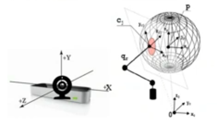
The reference frame is a 3 axis system that are usually connected by a body, an object or a system that can be used to acquire information or transmit information. For example a camera can be a reference frame, when you record a video, you are recording from a fixed point of view, the lenses of the camera, which has a mean direction. We can use the object frame (the camera) as reference for a robotic arm that gets information from it, so the camera becomes our reference frame.
Main concepts:
- Reference Frame.
- Position.
- Orientation.
Reference Frames Examples:
- Camera Reference Frame
- Multi joint hand fingertips frame
- Virtual world reference frame
Everything has a reference frame in our robotic task.
Main task in robotics: Represent a reference frame of an object into another object’s reference frame, that can be the world reference frame, the camera’s, sensor’s, …
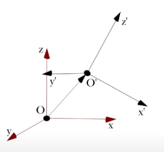
Pose of a Rigid Body
A rigid body is completely described in a reference frame by position and orientation.
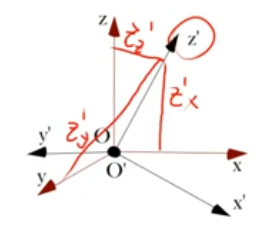
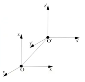 The position of point on the rigid body with respect to the coordinate frame () is expressed by a three dimensional vector .
Where are versors. (??? doesn’t make sense that they are versors ???)
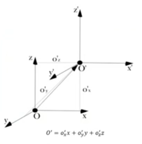
So the position of with respect to is defined as:
In this case:
- : is the World reference frame
- : is the Object reference frame
The idea is: I want to know in respect to . This because in my system is NOT allowed to change (being the world reference frame) so it’s perfect for referencing that can change.
While for the position of with respect to , we can use the position of each vector of the object frame with respect to the reference frame:
 We obtain a representation of rotation by the Rotation Matrix
Rotation Matrix
I can try to write something like this:
Where for example is defined as:
So, is defined as:
Rotation Matrix from reference frame to
Definition ‘Elementary Rotation’
Given 2 reference frames we define the Elementary Rotation of the frame A with respect to frame B as the rotation of only one axis of the frames.
The composition of multiple Elementary Rotation Matrix result in a complete Rotation Matrix
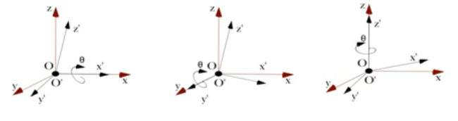
~ Example: Rotation along the axis
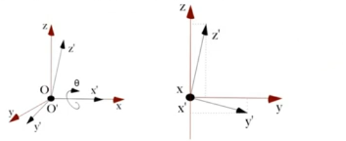
We rotate the frame with an angle of along the axis, as we can see in the second picture we can rewrite the rotation as:
~ Example: Other Elementary Rotations
Composition of Elementary Rotation
Each orientation could be composed by elementary rotations of the object frame with respect to the reference frame.
Successive rotations of an object about the object frame is obtained by Premultiplication of rotation matrices.
Successive rotations of an object about the reference frame is obtained by Postmultiplication of rotation matrices.
Where Premultiplication and Postmultiplication only mean when the Elementary Rotation Matrix is multiplied (if at the beginning or at the end).
Remember: The object frame is referenced to the reference frame
Rotation Matrices Descriptors
Rotation Matrices give a redundant description of frame orientation.
We can use other descriptors:
- Euler Angles.
- RPY Angles.
- Angle and Axis.
- Quaternion.
Euler Angles
I have to specify beforehand in which axis i will rotate: ~ex.: ZXZ Also all Euler Angles will do 3 elementary rotations:
Where for formality:
- “ROLL” : always means a rotation along the axis
- “PITCH” : always means a rotation along the axis
- “YAW” : always means a rotation along the axis
This are names that sailor uses for rotating the ships
~ Examples of Euler Angles Rotations:
- ZXZ (Most used for the Euler Angles, Standard for Euler Angles):
- ZYX (Roll Pitch and Yaw):
RPY Angles
Specific Euler Angeles: ZYX (Roll Pitch and Yaw):
Angle and Axis
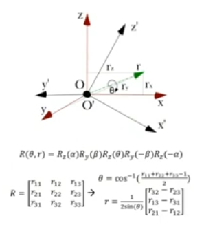
Where:
And:
- Where is the element of the Rotation Matrix
So for → → (Indeterminate). The Quaternion descriptor is more complicated but can avoid this problem
Quaternion
There is no possibility that 2 different quaternions give the same final rotation.
Let’s take an example: in the Angle and Axis descriptor formulas, we find that Now if then can be both equal to or .
Let’s now define and with respect to and as:
Where is a vector () so is , while is a scalar ()
Notice that:
And:
Homogeneous Transformation Matrix
The pose of an object, then a frame could be represented in another one by one only matrix called homogeneous transformation matrix:
First I resolve the problem of position then the problem of orientation.
- Solve the difference of and
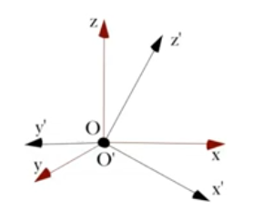
- Considering the and in the same center i calculate the Rotation Matrix
So a Pose is just a collection of Translation and Rotation.
The Transformation Matrix that change one pose to another is denoted as .
The 3 zeros elements in the last row are usually unchanged but sometimes they do change, when they do it’s because we want to impose the concept of prospective, for example when using a camera some dimensions are forcefully distorted (closer objects appear bigger).
The last element is often , but it can be changed to reference the scale of my robot or environment (, , , … when working with small robots, , , , for big robots)